13.4 DSI_V3 display board connector (CN2)
The 64-pin connector (CN2) supports DSI_V3 display add-on boards.
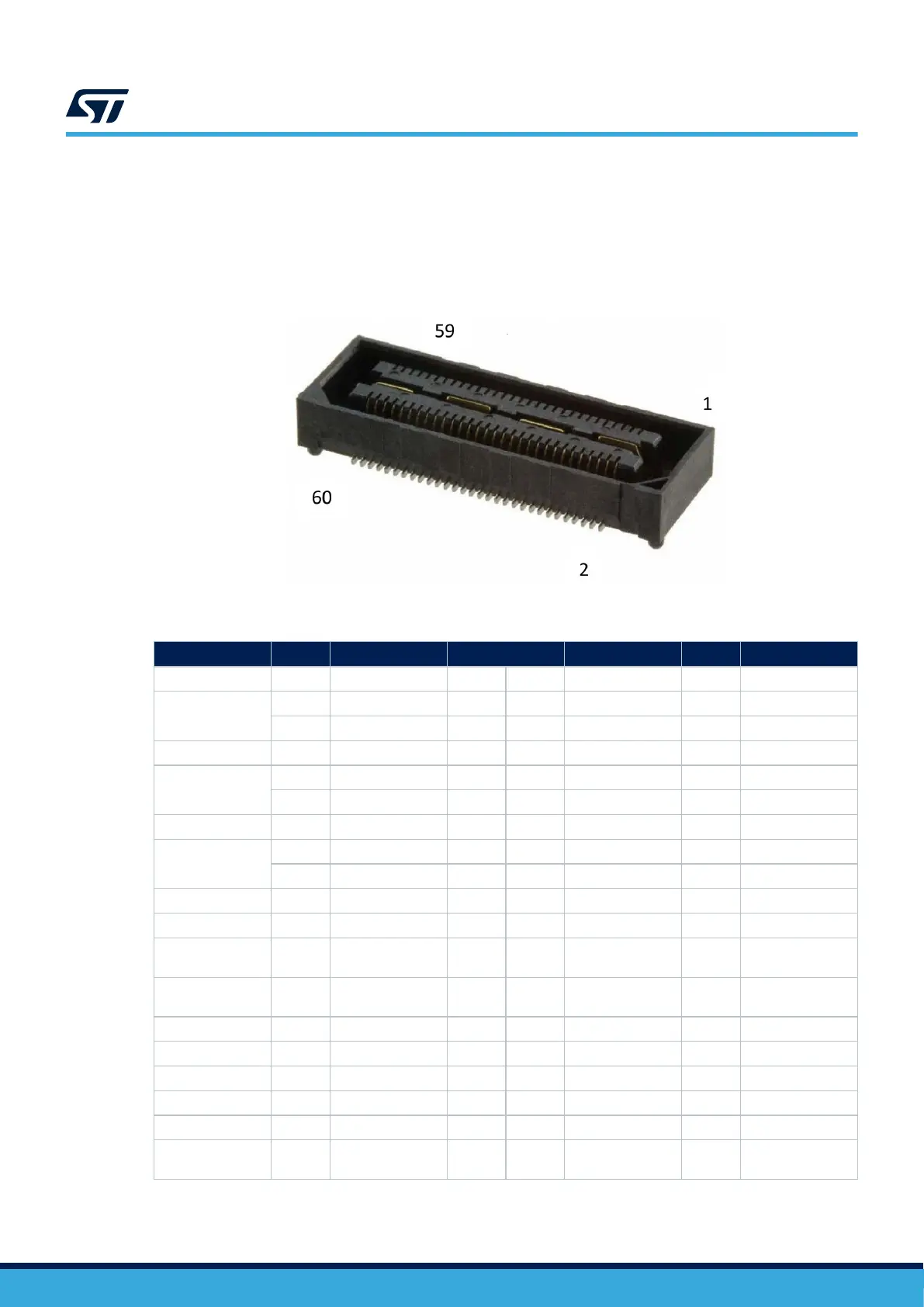
Pin 61 to 64 (central pads for ground reference) are not accessible when an add-on board is plugged in.
The MB1829 on-board connector reference is QSH-030-01-F-D-A from SAMTEC. The MB1835 on-board mating
connector is QTH-030-02-F-D-A (for a total height of 8 mm between boards).
Figure 29. DSI_V3 display connector (CN2)
Table 26. DSI_V3 connector pin assignment (CN2)
Function
GPIO Signal name Pin number (CN2) Signal name GPIO Function
General ground - GND 1 2 NC - -
Differential DSI
clock
(1)
- DSI.CK_N 3 4 DSI_TOUCH_INT PE8 Touch interrupt
- DSI.CK_P 5 6 GND - General ground
General ground - GND 7 8 DSI_D2_P - Not connected
Differential DSI
data 0
- DSI.D0_P 9 10 DSI_D2_N - Not connected
- DSI.D0_N 11 12 GND - General ground
General ground - GND 13 14 DSI_D3_P - Not connected
Differential DSI
data 1
- DSI.D1_P 15 16 DSI_D3_N - Not connected
- DSI.D1_N 17 18 GND General ground
General ground - GND 19 20 NC - -
Power output - 5V_LCD 21 22 DSI_SPI_CS PD8 SPI chip select
Power output - 5V_LCD 23 24 DSI_SPI_CLK
PB13/
PD10
SPI/USART clock
- - NC 25 26 DSI_SPI_MOSI
PD4/
PB10
SPI/USART data
- - BLGND 27 28 DSI_SPI_DCX PD11 SPI data/control
- - BLGND 29 30 NC - -
- - NC 31 32 RESERVED - -
- - NC 33 34 NC - -
- - NC 35 36 3V3_LCD - 3.3 V voltage
- - NC 37 38 VDD_LCD -
VDD voltage
reference (1.8 V)
UM2967
DSI_V3 display board connector (CN2)
UM2967 - Rev 1
page 43/68