To use CN11 or CN3 connector (SWD/SWO/JTAG/USART interface), here are the things to consider and
configure:
1. Put the embedded STLINK-V3E in Reset mode: Move the TRNST jumper (JP5) on the STLK_NRST
header (JP6), no data transfer is possible from USB ST-LINK. This allows using either CN11 or CN3
without the risk of signals conflict with STLINK-V3E on any interface.
2. Because STLINK-V3E is in Reset mode, you have also to remove the jumper (JP4) from the STLK position
and put it in any other position according to your required configuration (refer to Section 9.2 Power source
selection and Section 9.1 Power diagram).
3. If you use the SWD interface in 2‑wire mode (without SWO), no need for further modifications.
4. If you use the SWD interface in 3‑wire mode (with SWO), or JTAG interface (with JTDO), disconnect SB33
and connect it to SB34.
Note: JTDI can be used by default because UCPD.CC1 is not used.
Note: CN11 and CN3 connectors provide access to the PG10-NRST pin of the STM32U5A9NJH6Q
microcontroller, but do not offer access to the NJRST function. NJRST function is only accessible on
PB4 on CN9 pin 8, and it is exclusive to SDMMC2_D3.
5. If you want to use the USART1 bootloader interface: Connect your tool to RX/TX on pin 13/14 of CN11 (it
must be 1.8V compatible). (Or, If STDC14 is used as CN11, just connect the MIPI14 cable to your 1.8V
compatible tool).
6. Power up the board: Connect your Power source to the board.
7. Use any of debug (CN11) or TAG (CN3) connectors for STM32U5A9 connection: Use a MIPI10 or MIPI14
cable to connect on debug (CN11) or use a TAG connect LLC: TC2050-IDC-NL cable to connect on
TAG footprint (CN3). Reminder: The board is 1.8 V by default, so only use adequate/compatible tools to
connect.
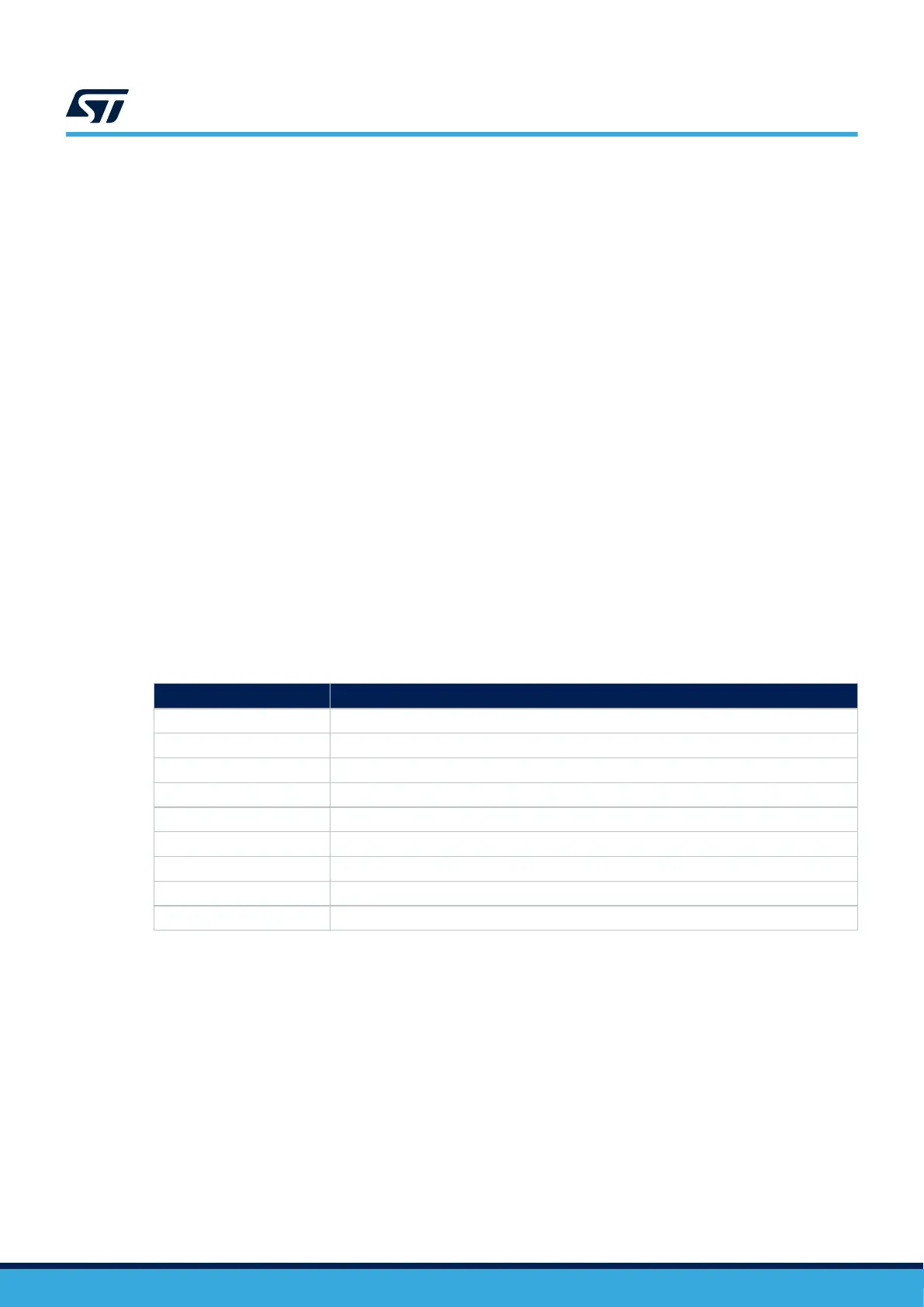
12.14.2 SWD, SWO, JTAG, and USART I/O interface
Table 21. SWD, SWO, JTAG, and USART function I/O interface
PIO
Configuration
PIO Configuration
PA13 T.SWDIO (SWDIO/JTMS)
PA14 T.SWCLK (SWCLK/JTCK)
PB3 T.SWO (SWO/JTDO) - optional
PA15 T.JTDI (JTDI)
PB4 NJTRST – not used, available on CN9 only
NRST NRST
PA9 TVCP_TX (USART1_TX) – access on STDC14 footprint
PA10 TVCP_RX (USART1_RX) – access on STDC14 footprint
UM2967
SWD debug/program/trace and JTAG/USART
UM2967 - Rev 1
page 38/68