51TS 410, TS 420
8. Ignition system
Exercise extreme caution while
carrying out maintenance and repair
work on the ignition system. The
high voltages which occur can
cause serious or fatal accidents.
Troubleshooting on the ignition
system should always start with the
spark plug, b 4.4.
– Remove the fan cover, b 7.3.
The electronic ignition system
basically consists of an ignition
module (1) and flywheel (2).
8.1 Ignition module
The ignition module accommodates
all the components required to
control ignition timing. There are
two electrical connections on the
coil body:
1
2
370RA188 TG
1
2
370RA189 TG
– High-voltage output (1) with
permanently fitted ignition lead
– Connector tag (2) for the short
circuit wire.
Testing in the workshop is limited to
a spark test. A new ignition module
must be installed if no ignition spark
is obtained (after checking that the
wiring and stop switch are in good
condition), b 8.1.1.
Ignition timing is fixed and cannot
be adjusted during repair work.
Since there is no mechanical wear
in these systems, ignition timing
cannot get out of adjustment during
operation.
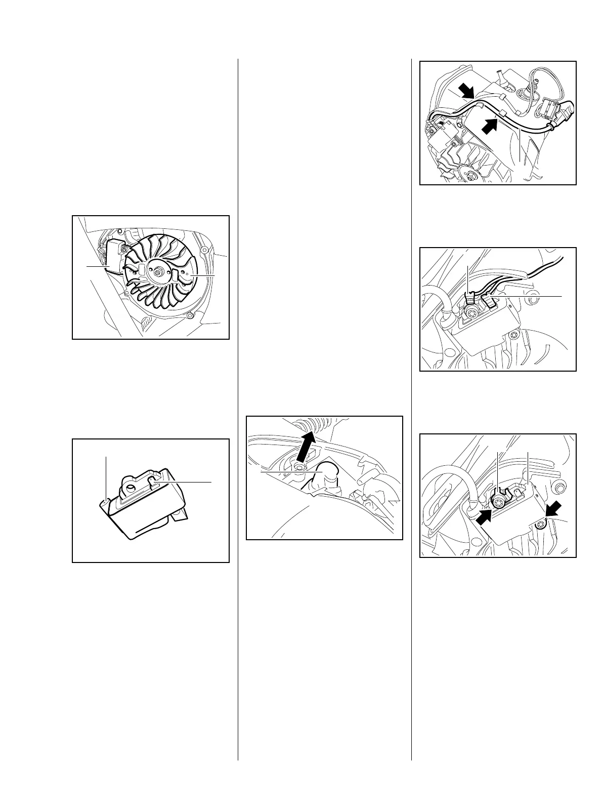
8.1.1 Removal and installation
– Remove the shroud, b 7.4.
– Remove the fan cover, b 7.3.
: Remove the spark plug boot (1).
370RA058 TG
1
: Take the ignition lead (1) out of
the cable guides (arrows).
: Disconnect the short circuit
wire (1) and ground wire (2).
: Take out the screws (arrows).
– Remove the connector tag (1)
and ignition module (2).
1
370RA190 TG
1
2
370RA191 TG370RA192 TG
21

 Loading...