3TS 410, TS 420
1. Introduction
This service manual contains
detailed descriptions of all the
typical repair and servicing
procedures for this power tool.
Refer to the illustrated spare parts
lists during all repair work. These
lists show the installation position
and order in which the individual
parts and modules should be
assembled.
Refer to the latest edition of the
relevant parts list to check the part
numbers of any replacement parts
required.
A fault on the machine may be due
to several causes. To help locate
the fault, consult the chapter on
"Troubleshooting" and the
"STIHL Service Training System"
for all function groups.
Refer to the "Technical Information"
bulletins for engineering changes
which have been introduced since
publication of this service manual.
Technical information bulletins also
supplement the parts list and
service manual until an updated
edition is issued.
The special tools mentioned in the
descriptions are listed in the chapter
"Special Servicing Tools" of this
manual. Use the part numbers to
identify the tools in the STIHL
Special Tools manual.
It lists all the special servicing tools
currently available from STIHL.
Symbols are included in the text and
pictures for greater clarity.
The meanings are as follows:
In the text:
: = Action to be taken as shown in
the illustration above the text
– = Action to be taken but not
shown in the illustration above
the text
In the illustrations:
A Item pointer (short arrow)
aDirection of movement
(long arrow)
b 4.2 = Reference to another
chapter, i.e. to chapter 4.2
in this case
Service manuals and technical
information bulletins are intended
exclusively for the use of properly
equipped repair shops. They must
not be passed on to third parties.
Servicing and repairs are made
considerably easier by mounting the
machine on the assembly stand (3)
5910 890 3100. For this purpose,
secure the support (2)
5910 850 1650 to the assembly
stand with two screws (1) and
washers.
The screws must not protrude, as
they may damage the housing when
the machine is clamped, depending
on model.
This step is not necessary when
using the new assembly stand
5910 890 3101, as the support is
already mounted on it.
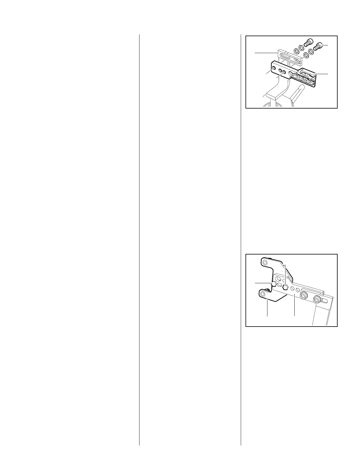
The clamping plate (1)
4238 890 2100 is secured to
the support (2) with two M8x20
screws (3) and washers.
1
2
3
219RA000 TG
3
1
2
3
370RA000 TG

 Loading...