89TS 410, TS 420
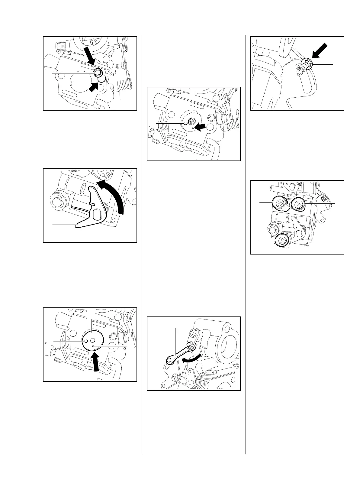
: Press the cap (1) into the hole
(arrow) until it is flush with the
carburetor. The cap must not
protrude over the sealing face of
the carburetor.
: Turn the throttle shaft (1)
approx. ½ turn counterclockwise
until the flat side of the throttle
shaft comes into view. The
throttle shaft is now pre-
tensioned.
– Hold the throttle shaft in this pre-
tensioned position.
370RA005 TG
1
370RA392 TG
1
370RA393 TG
2
1
3
: Lay the throttle shutter (1) onto
the flat side of the throttle shaft so
that the hole (2) is on the left and
the small hole (3) is below the
throttle shaft.
– Coat the screw with screw
locking paint, b 14.
: Insert a new screw (1) and screw
it in slightly.
– Close the throttle shutter and
center it in the hole in the
carburetor housing.
The hole (2) must be on the left and
the small hole (arrow) below the
screw.
– Tighten down the screw.
– Check correct functioning and
easy movement.
: Attach the rod (1).
370RA394 TG
1
2
370RA397 TG
1
: Install the E-clip (1).
– Reassemble remaining parts in
reverse order.
12.3.8 Adjusting screws
There are three adjusting screws on
the carburetor:
H
= High speed adjusting screw (1)
L = Low speed adjusting screw (2)
LA = Idle speed adjusting screw (3)
If the carburetor setting can no
longer be adjusted, this may also be
due to the adjusting screws.
The high speed adjusting screw H
has a limiter cap which must be
removed before removing the
screw.
Always fit a new limiter cap.
– Remove the carburetor, b 12.2.
– See also troubleshooting on the
carburetor, b 4.5.
370RA147 TG
1
370RA398 TG
1
3
2

 Loading...