41TS 410, TS 420
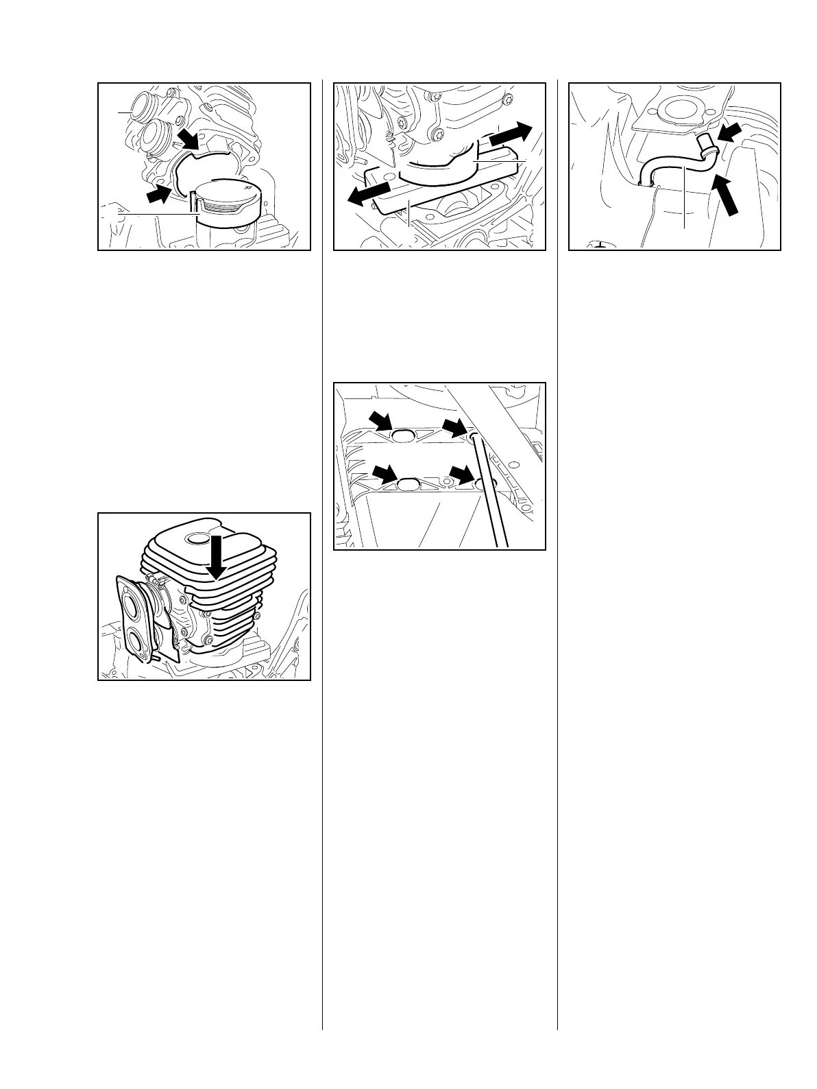
: Align the cylinder so that the
cylinder inlet port (1) faces
towards the handle and the
recesses (arrows) engage in the
tightening ring (2).
When fitting the cylinder over the
piston, ensure that the tightening
ring encloses the piston securely
and that none of the piston rings
protrudes, otherwise it may break.
– Install the intake elbow, b 12.6.
: Slide the cylinder over the piston,
pushing the tightening ring
downwards at the same time.
370RA129 TG
1
2
370RA130 TG
: Remove the tightening ring (1)
and wooden assembly block (2).
Ensure that the cylinder gasket is
correctly positioned.
– Slide the cylinder into position as
far as possible and hold it there.
: Insert the pan head screws
through the openings (arrows) in
the tank housing and screw them
in. Fit the pan head screw in the
molded hosing.
– Check the position of the cylinder
gasket.
– Tighten the screws down
crosswise.
– Tightening torques, b 3.5.
370RA131 TG
1
2
370RA119 TG
: Connect the impulse hose (1) to
the connector (arrow).
– Reassemble remaining parts in
reverse order.
7.6 Crankshaft
7.6.1 Removal and installation
– Remove the cast arm with guard,
b 5.2.
– Remove the ignition module,
b 8.1.
– Remove the flywheel, b 8.5.
– Remove the clutch drum, b 6.1.
– Remove the handlebar, b 10.5.
– Empty the fuel tank, b 1.
– Remove the tank housing,
b 12.9.
– Remove the cylinder, b 7.5.
– Remove the piston, b 7.7.
Always fit new grooved ball
bearings and oil seals when
removing the crankshaft.
1
370RA133 TG

 Loading...