74 TS 410, TS 420
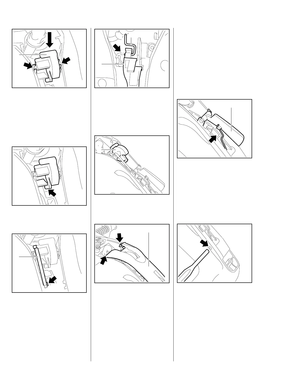
– Align the switch shaft. The larger
bearing journal must point
towards the switch.
: Press the switch shaft (1) into the
bearing points (arrows) until it
clicks into place.
The peg (arrow) must engage in the
throttle trigger.
: Lay the leaf spring (1) on the
cams of the switch shaft and
press it into the mount (arrow).
– Hook the torsion spring into the
trigger interlock.
370RA298 TG
1
370RA299 TG370RA300 TG
1
– Take the throttle rod out of the
guide.
: Hook the throttle rod (1) into the
throttle trigger (arrow).
– Set the switch shaft (1) to
position "
0".
: Guide the handle molding (1) into
position under the pegs (arrows).
– Insert and tighten down the
screw.
– Tightening torques, b 3.5.
370RA112 TG
2
1
370RA302 TG
1
370RA303 TG
1
– Check correct functioning: the
switch shaft must actuate the
switch when in position "
0"; it
must engage and slightly lift the
throttle trigger when in position
"START".
11.2 Throttle trigger/trigger
interlock, removal and
installation
– Remove the handle molding,
b 11.1.1.
– Unhook the torsion spring
(arrow).
: Pull the trigger interlock (1) out of
the bearing points.
: Drive the pin (arrow) out with a
drift.
370RA304 TG
1
370RA305 TG

 Loading...