www.stryker.com 6390-009-002 REV D 41
Service
Cover removal and replacement (Continued)
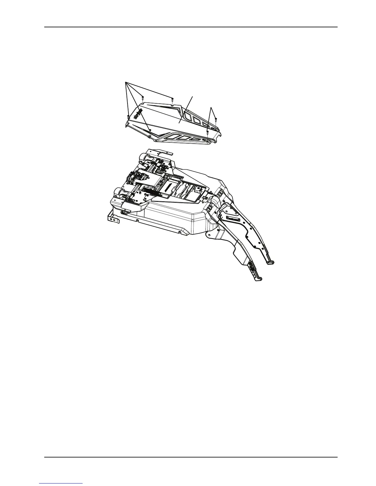
1. Using a T25 Torx driver, remove the six screws (A) that secure the trolley top cover (B) (Figure 6 on page 41).
Figure 6: Trolley top cover
2. Using a T25 Torx driver, remove the three screws (C) left side cover (D) (Figure 7 on page 42).
3. Using a 5/32" hex wrench, remove one hex head screw (E) from the top of the left side cover (D) (Figure 7 on page
42).
4. Remove the cover. Save the side cover, left and all screws for reinstallation.
 Loading...