44 6390-009-002 REV D www.stryker.com
Service
Manual release button assembly removal and replacement (Continued)
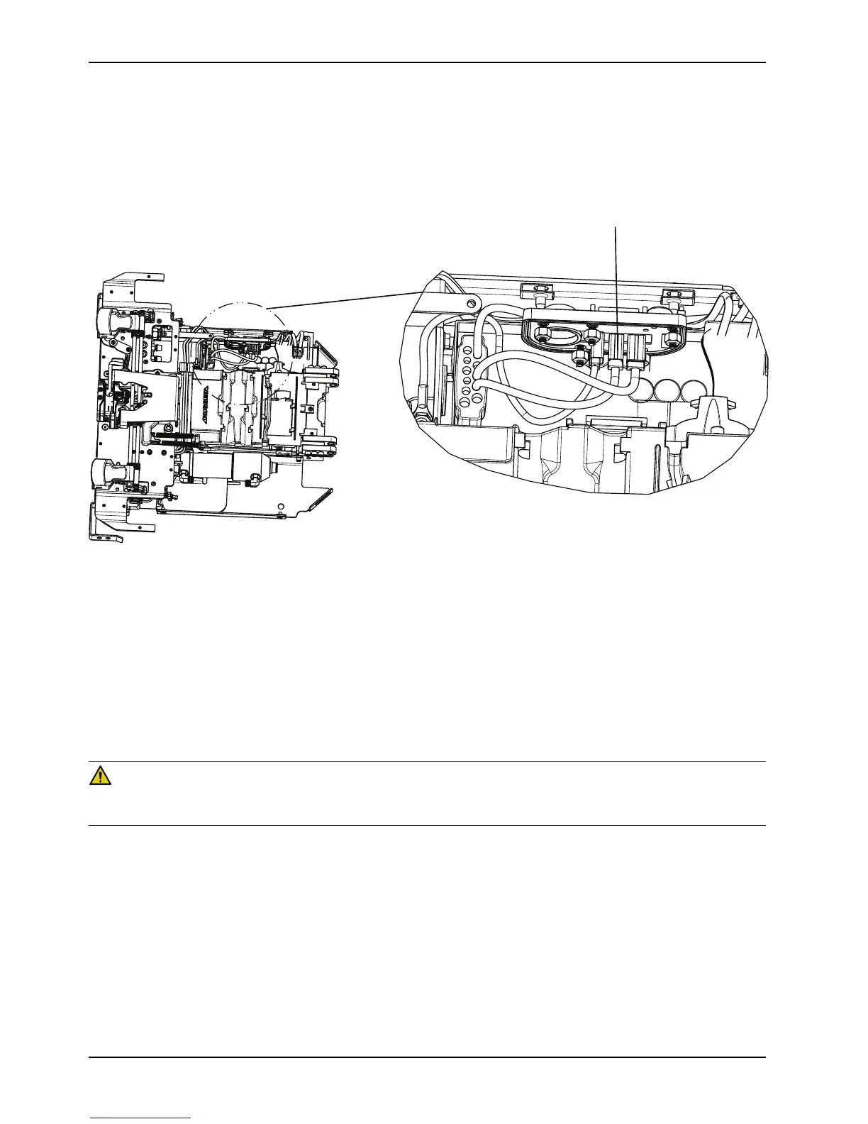
7. Unplug the cables from the master On/Off switch (D) and remove the manual release button assembly (Figure 9 on
page 44).
Note: Make note of the cable connection locations, so they do not get mixed up.
Figure 9: On/Off switch cable locations
8. Reverse steps to reinstall.
9. Verify proper operation of the product before returning it to service.
Control board assembly removal and replacement
Tools required
• 3/32" hex wrench
• ESD
WARNING
ESD precautions should be taken when handling the control board. For more information about ESD protection, contact
Stryker Technical Support at (800) 327-0770.
Procedure
1. Remove the manual release button assembly. See Manual release button assembly removal and replacement on
page 42.
2. Using a 3/32" hex wrench, loosen (do not remove) the two screws (A) that secure the main cable assembly (B) to
the control board assembly (Figure 10 on page 45).
3. Unplug all of the other cables from the control board assembly (C) and then remove the control board assembly
(Figure 10 on page 45). Discard the control board assembly.
Note: Do not dispose of as unsorted municipal waste. Refer to your local distributor for return or collection systems
available in your country.
 Loading...