42 6390-009-002 REV D www.stryker.com
Service
Cover removal and replacement (Continued)
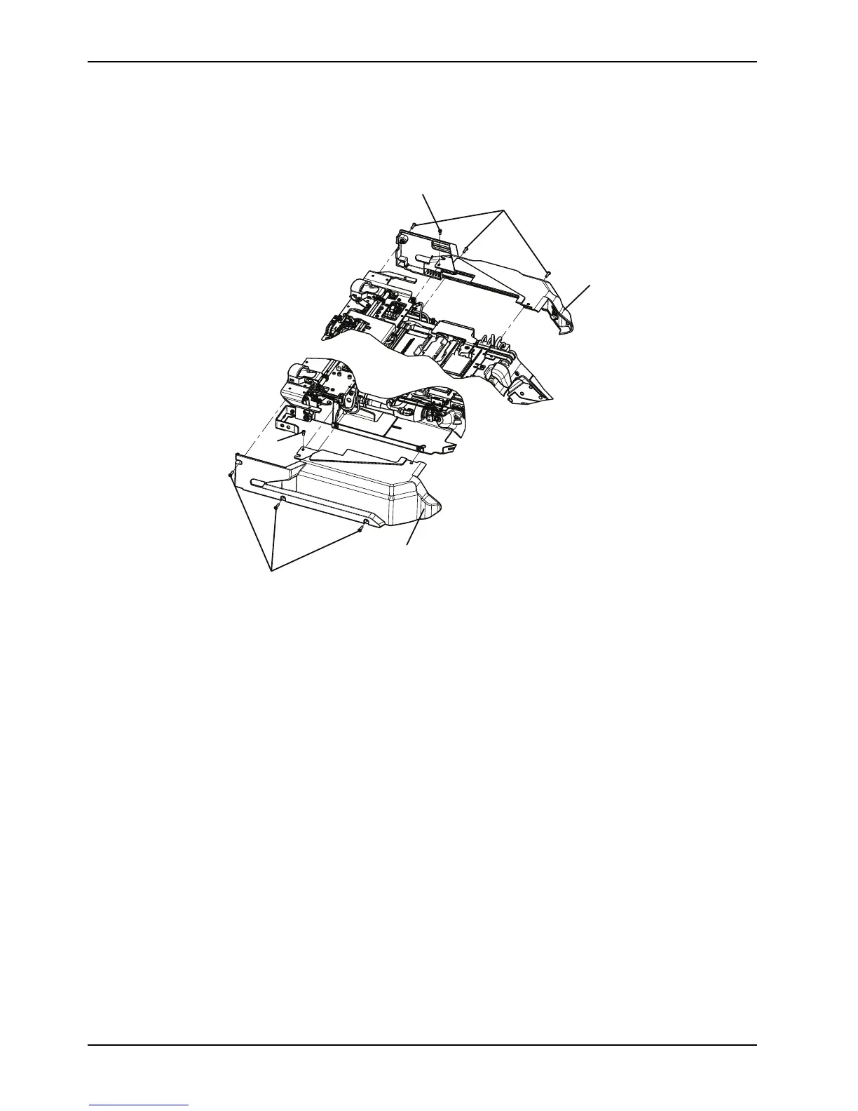
5. Repeat steps 2-4 to remove the side cover, right (F) (Figure 7 on page 42).
Figure 7: Trolley side covers
6. Reverse steps to reinstall.
7. Verify proper operation of the product before returning it to service.
Manual release button assembly removal and replacement
Tools required
• T25 Torx drive
• 5/32" hex wrench
Procedure
1. Pull the trolley assembly out of the patient compartment until it locks into the loading position.
2. Remove the trolley covers. See Cover removal and replacement on page 40.
3. Press the main power button to turn the product off.
4. Remove the slic pin (A) from the switch/bracket assembly (Figure 8 on page 43).
5. Using a T25 Torx driver, remove the two button head cap screws (B) that secure the manual release button bracket
to the trolley frame (Figure 8 on page 43).