www.stryker.com 6390-009-002 REV D 45
Service
Control board assembly removal and replacement (Continued)
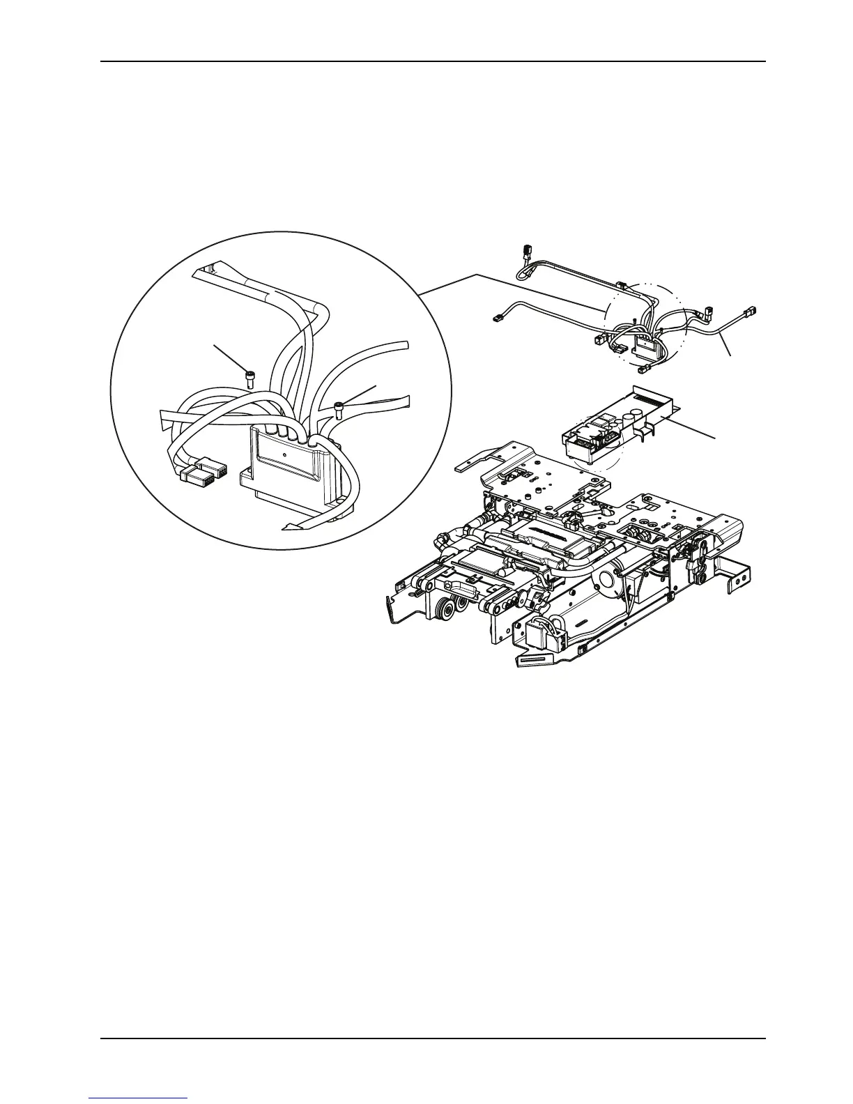
4. Align the control board assembly tabs with the holes in bottom pan, left to install the new control board assembly.
Make sure that all of the cables are routed correctly.
5. Reverse steps to reinstall.
6. Verify proper operation of the product before returning it to service.
Figure 10: Control board assembly
Master on/off switch replacement
Tools required
• 1/32" Nut driver
Procedure
1. Remove the manual release button assembly. See Manual release button assembly removal and replacement on
page 42.
2. Using an 11/32" nut driver, remove the five Fiberlock hex nuts (A) that secure the master On/Off switch (B) to the
manual release button bracket (C). Discard the master On/Off switch (Figure 11 on page 46)
Note: Do not dispose of as unsorted municipal waste. Refer to your local distributor for return or collection systems
available in your country.
3. Reverse steps to reinstall.
Note: Do not overtighten the nuts.
4. Verify proper operation of the product before returning it to service.

 Loading...