66 6390-009-002 REV D www.stryker.com
Service
Pump / motor assembly replacement (Continued)
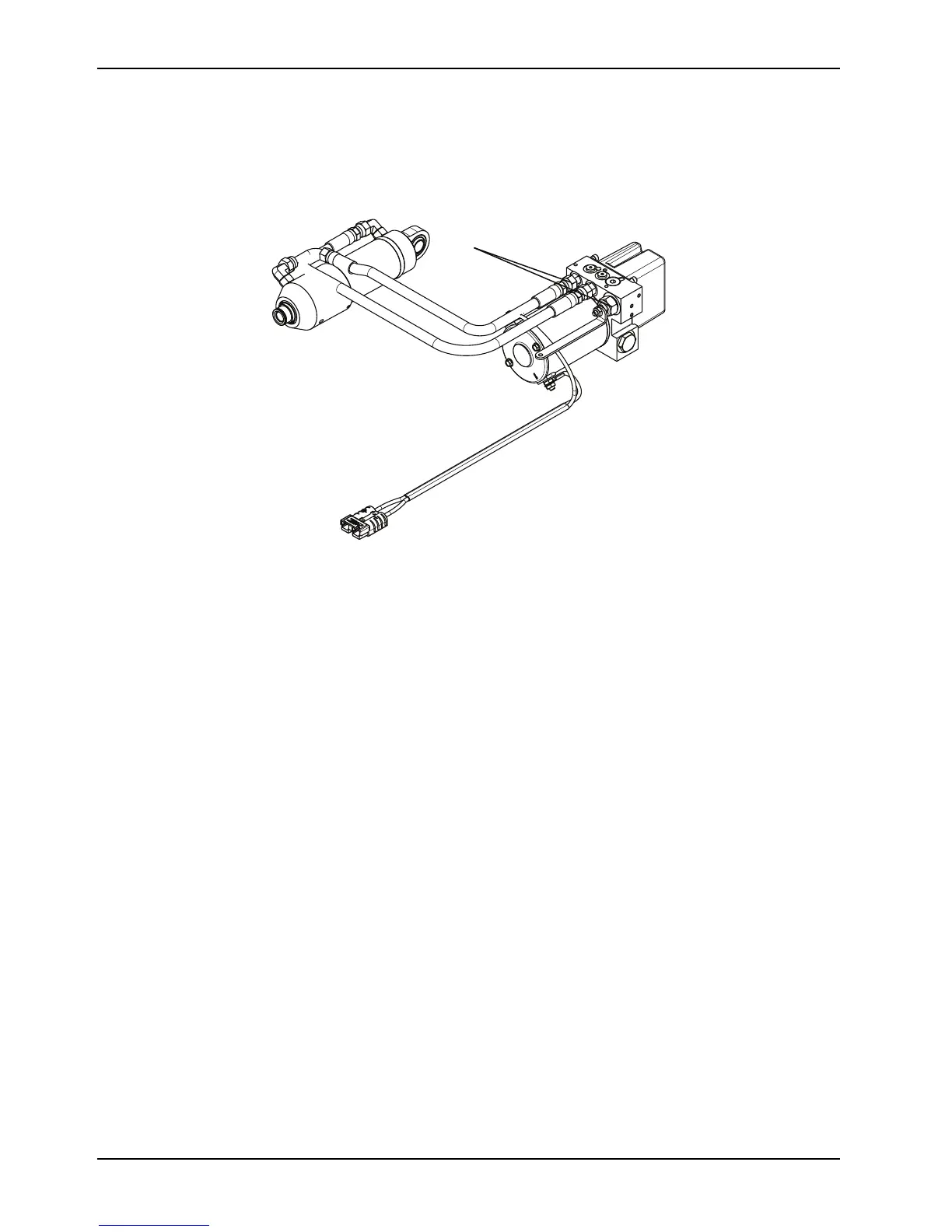
3. Using two 9/16" combination wrenches, loosen (do not remove) the hose end connectors (A) from the manifold to
remove both hoses (Figure 34 on page 66).
Note: Hydraulic fluid will leak from the cylinder and hoses. Lay down towels to catch fluid.
Figure 34: Hydraulics assembly hose end connectors
4. Reverse steps to reinstall.
5. Verify proper operation of the product before returning it to service.
Motor cable removal and replacement
Tools Required
• 7/16" combination wrench
Procedure
1. Pull the trolley assembly out of the patient compartment until it locks into the loading position.
Note: This makes working on the product easier, but is not required.
2. Remove the trolley covers. See Cover removal and replacement on page 40.
3. Remove the hydraulics assembly. See Hydraulics assembly removal and replacement on page 48.