68 6390-009-002 REV D www.stryker.com
Service
Motor replacement (Continued)
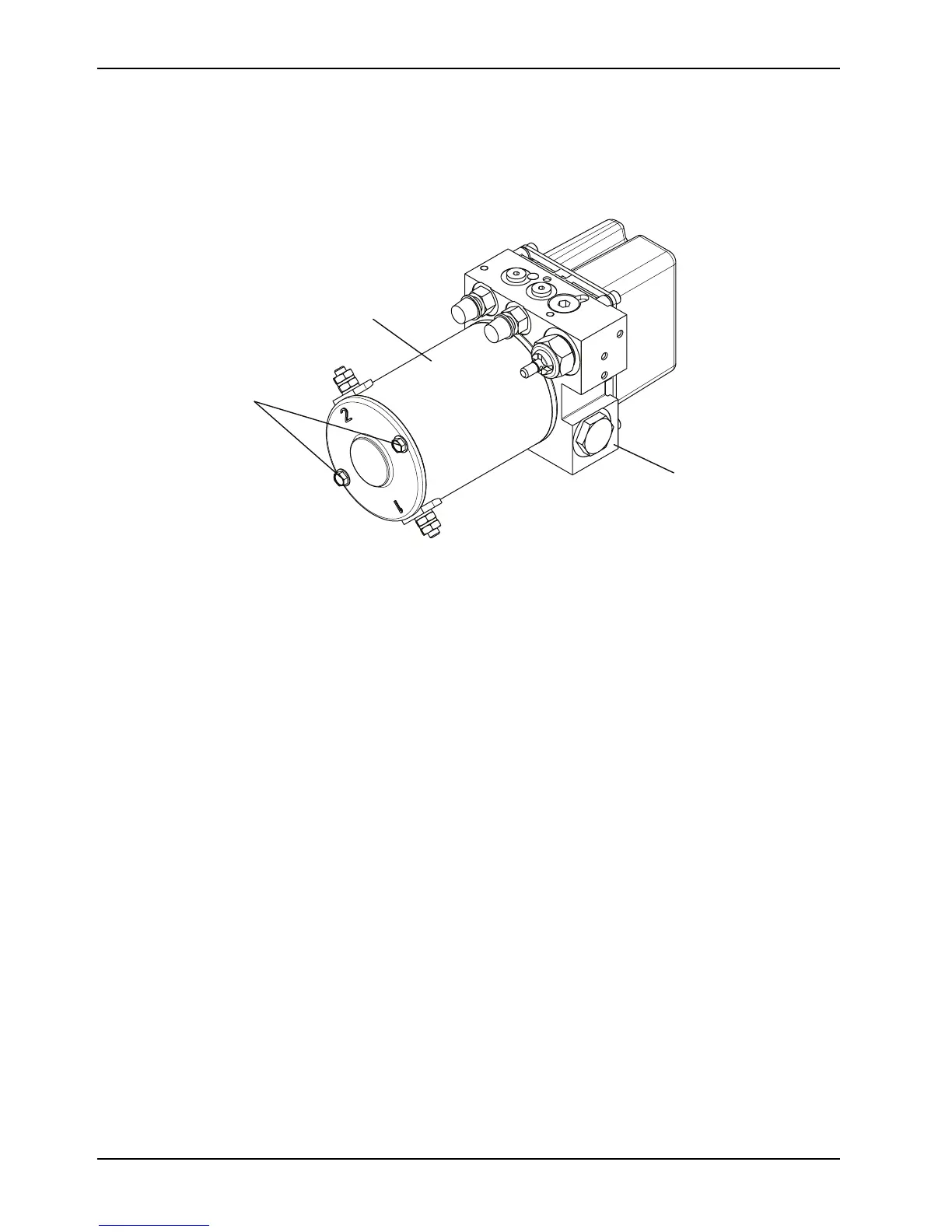
4. Using a 7/16'' combination wrench, remove the two bolts (A) that secure the motor (B) to the hydraulic manifold
assembly (C) (Figure 36 on page 68).
Note: During reinstallation, do not overtighten the bolts.
Figure 36: Motor replacement parts
5. Reverse steps to reinstall.
6. Verify proper operation of the product before returning it to service.
Pressure compensated flow control valve replacement
Tools Required
• 1/4'' hex wrench
• Needle nose pliers
Procedure
1. Pull the trolley assembly out of the patient compartment until it locks into the loading position.
Note: This makes working on the product easier, but is not required.
2. Remove the trolley covers. See Cover removal and replacement on page 40.
3. Remove the hydraulics assembly. See Hydraulics assembly removal and replacement on page 48.

 Loading...