58 6390-009-002 REV D www.stryker.com
Service
Trolley position sensor (TPS) replacement (Continued)
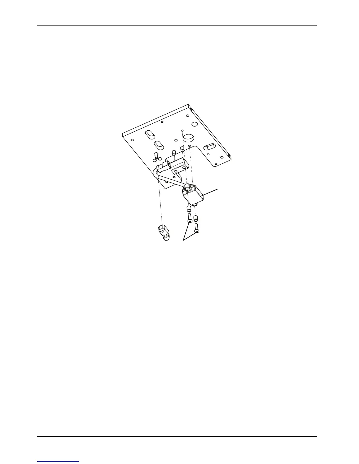
7. Using a 1/4" ratchet and a T25 Torx driver, remove the two button head cap screws (G) that secure the TPS
assembly (H) (Figure 25 on page 58).
Notes
• Slightly lift up on the trolley mechanism arm to pull the cable through to remove the TPS. Discard the TPS.
• Do not dispose of as unsorted municipal waste. Refer to your local distributor for return and/or collection
systems available in your country.
Figure 25: TPS assembly bottom view
8. Reverse steps to reinstall.
9. Verify proper operation of the product before returning it to service.
Flat roller and V-guide roller replacement
Tools required
• 3/8" drive ratchet
• 1/4" socket
• Torque wrench (in-lb) > 317 in-lb
Procedure
1. Remove the trolley. See Trolley removal on page 37.
2. Carefully set the trolley upright on its head end (Figure 26 on page 59).
Note: Do not tip the trolley upside down, forward or onto its side.
3. Using a 1/4" socket with a 3/8" drive ratchet, loosen (do not remove) the pivot bolt that secures the bad roller to the
trolley.
Note: The V-guide rollers are on the patient right side (five rollers) (A) and the flat rollers are on the patient left side
(two rollers) (B) (Figure 26 on page 59).
 Loading...