48 6390-009-002 REV D www.stryker.com
Service
Trolley actuator assembly replacement (Continued)
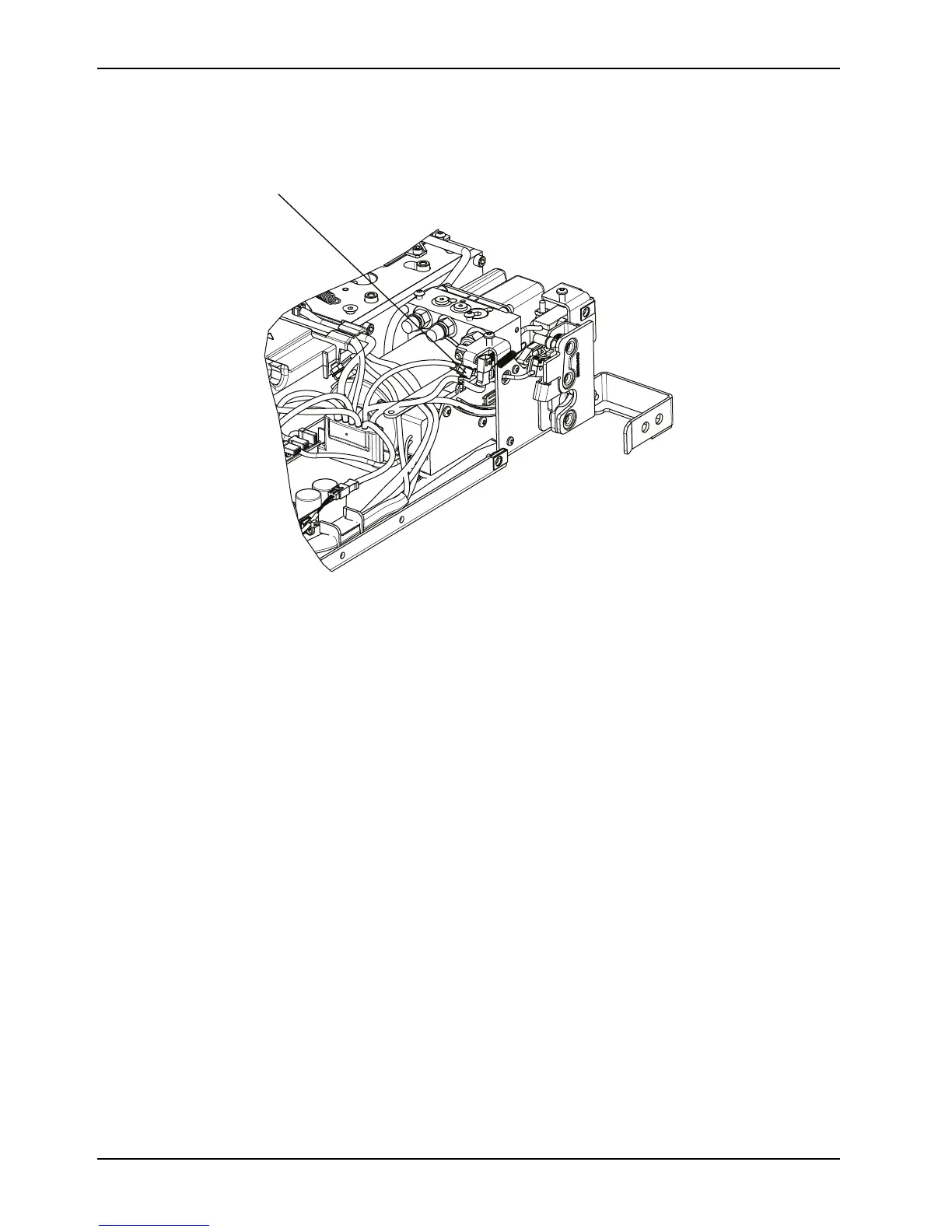
Figure 13: Main cable assembly
Hydraulics assembly removal and replacement
Tools Required
• T20 Torx driver
• T25 Torx drive
• 1/4" hex wrench
• 3/16" hex wrench
• 1/2" combination wrench
• Diagonal pliers
Procedure
1. Remove the control board assembly. See Control board assembly removal and replacement on page 44.
2. Remove the trolley actuator assembly. See Trolley actuator assembly replacement on page 46.
3. Unclip the cables from the trolley routing tray and the hydraulic hoses.
4. Unplug the USB quick connect and the D+L-L lock switch cable from the main cable.
5. Position the main cable assembly toward the center of the trolley to allow clearance.