www.stryker.com 6390-009-002 REV D 49
Service
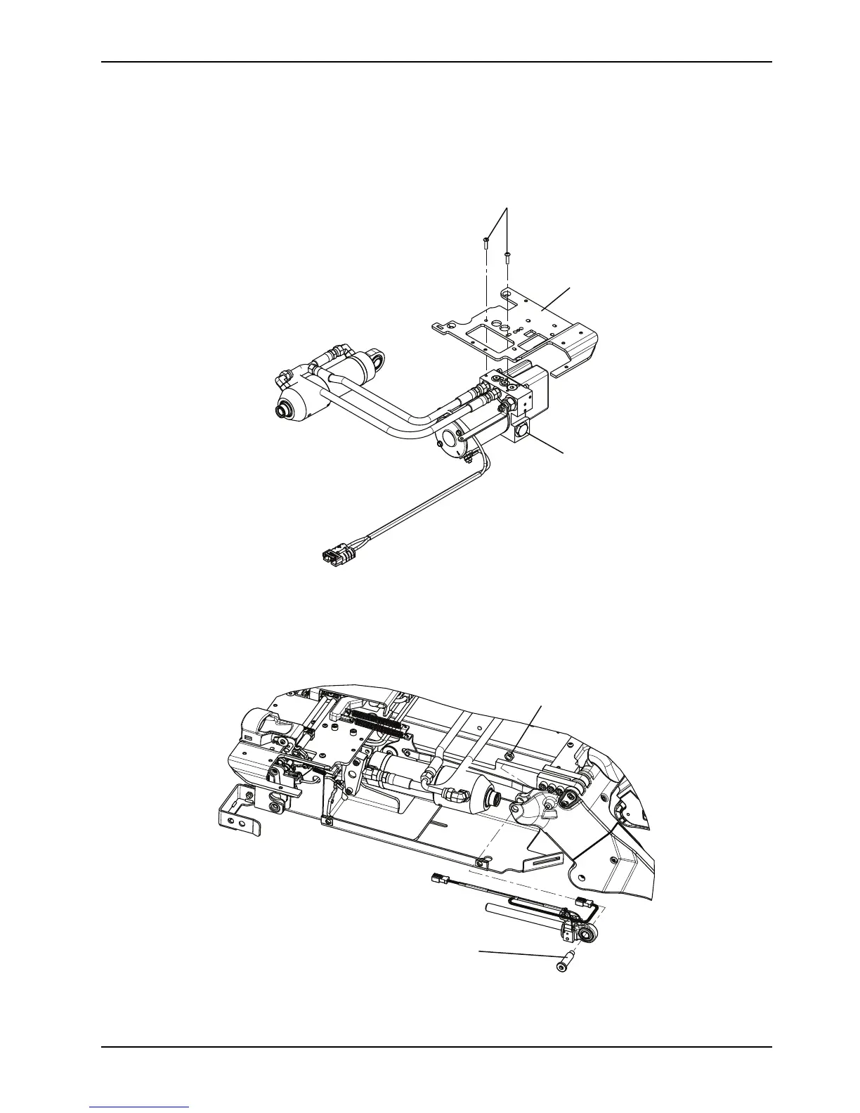
Hydraulics assembly removal and replacement (Continued)
6. Using a T25 Torx driver, remove the two screws (A) that secure the hydraulics assembly (B) to the wing plate, left
(C) (Figure 14 on page 49).
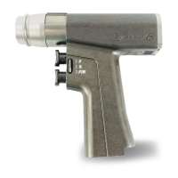
Figure 14: Hydraulics assembly
7. Pull outward to remove the pump assembly and set the pump assembly on top of the wing plate, left.
8. Using a 1/4" hex wrench and a 1/2" combination wrench, remove the end cap cylinder pin (D) and nut (E) (Figure
15 on page 49).
Figure 15: End cap cylinder pin and nut locations