18 6390-009-002 REV D www.stryker.com
Preventive maintenance
Installation checklist (Continued)
Slide the manual lock override closest to the foot end on the transfer and push the transfer out toward the foot
end. Make sure that the transfer can be unlocked.
Fully extend Power-LOAD out of the vehicle patient compartment.
Slide the manual lock override closest to the head end on the transfer and push the transfer in toward the head
end. Make sure that the transfer can be unlocked.
Visually inspect the head end transfer bumpers to make sure that they are installed flush to the outer edge of
the transfer assembly with no signs of misalignment or improper installation.
Visually check that all bolts and screws are tight, with no signs of protruding or missing fasteners.
Push on the head end pawl and use the foot end release lever to activate the head end pin to make sure that
they move freely and do not bind after you let go.
For Type II ambulances or if the cot center line is 17.5 in. (44.5 cm) or less from the vehicle wall, make sure that
the optional wheel guide assembly (6390-027-000) is installed. Mark N/A if the wheel guide is not required.
Press the main power button to turn the product off. You may need to turn the product on and then off to make
sure that Power-LOAD is off and not in sleep mode.
Note: If you will not use Power-LOAD for a week or more, press the main power button to turn the product off and avoid
draining the battery. You may need to turn the product on and then off to make sure that Power-LOAD is off and not in
sleep mode.
Product serial number:
Installed by: Date:
Inspected by: Date:
Note: Maintain a copy of this record for at least seven years.
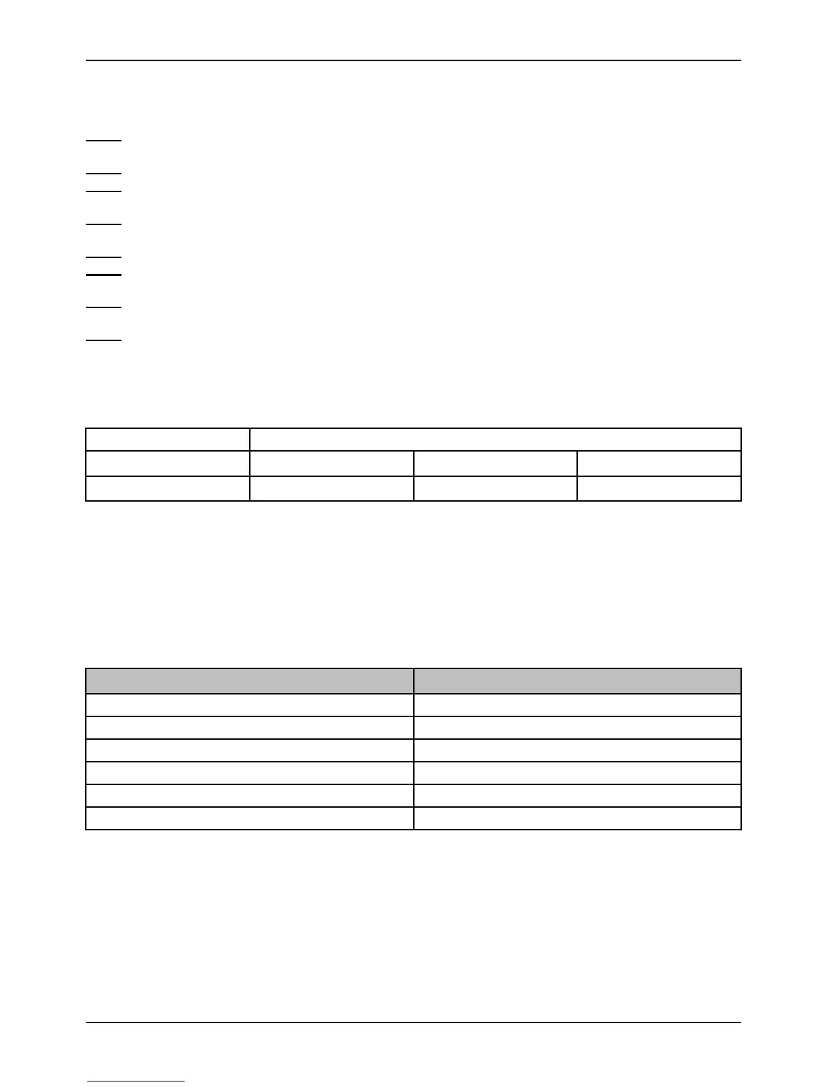
Flat roller and V-guide part replacement schedule
You must replace the flat roller and V-guide parts every 14,110 calls. This is to make sure that the Power-LOAD
remains functional. Follow this call volume time table to remain compliant with this requirement. The time table will also
help plan appropriate service intervals.
Calls per day
Months
6 80
7-8 60
9-10 48
11-12 40
13 36
14-15
30
Transfer lock bearing part replacement schedule
You must replace the transfer lock bearing parts every 3,653 calls. This is to make sure that Power-LOAD remains
functional. Follow this call volume time table to remain compliant with this requirement.