ix
Figures
FIGURE 1-1 Sun Fire V210 Server 1–2
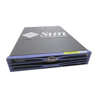
FIGURE 1-2 Sun Fire V240 Server 1–3
FIGURE 1-3 Location of Status Indicators (Sun Fire V210 Server) 1–6
FIGURE 1-4 Location of Front Panel Features (Sun Fire V240 Server) 1–9
FIGURE 1-5 Location of Hard Drive Service Indicators 1–11
FIGURE 1-6 Location of the Keyswitch (Sun Fire V240 Server) 1–15
FIGURE 1-7 Keyswitch Positions (Sun Fire V240 Server) 1–16
FIGURE 1-8 I/O Ports (Sun Fire V210 Server) 1–17
FIGURE 1-9 I/O Ports (Sun Fire V240 Server) 1–17
FIGURE 1-10 Location of Network Status Indicators 1–18
FIGURE 1-11 System Prompt Flow Diagram 1–21
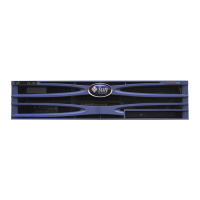
FIGURE 2-1 Opening the Bezel (Sun Fire V210 Server) 2–3
FIGURE 2-2 Opening The Bezel (Sun Fire V240 Server) 2–3
FIGURE 2-3 Inserting a System Configuration Card (Sun Fire V210 Server) 2–7
FIGURE 2-4 Installing a Hard Drive (Sun Fire V210 Server) 2–8
FIGURE 2-5 Removing a DVD-ROM Drive (Sun Fire V240 Server) 2–14