12
No. Name
A Top air inlet
B Indicator panel
C DC knob switch. Disconnect the DC load switch.
D Emergency stop button. In case of emergency, press this button to open the
AC circuit breaker and DC load switch.
E Base
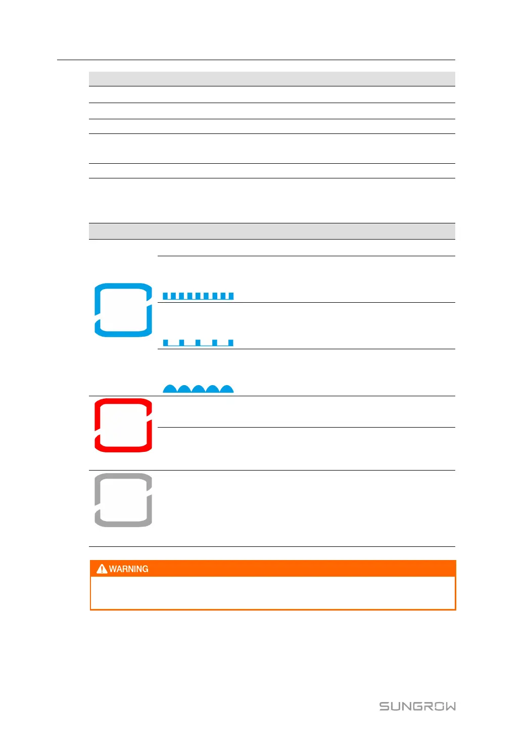
LED Indicator
table 3-1 Indicator Status Description
Color Status
Description
Blue
Steady on The inverter is in grid-connected operation.
Fast blinking (in-
terval: 0.2s)
WiFi connection is established and data communi-
cation is in process. No fault is detected.
Slow blinking (in-
terval: 0.5s)
The inverter is in a deep standby state.
Glowing and fad-
ing (interval: 2s)
The DC and AC side are powered on, or the AC
side is powered on, the inverter is in a standby or is
starting (not connected to the grid)..
Red
Steady on
A fault occurred and the system cannot be con-
nected to the grid for power generation.
Blinking (Interval
0.2s)
WiFi connection is established and data communi-
cation is in process. A fault is detected.
Grey
Off
The AC and DC power are disconnected.
Voltage may still be present in DC side circuits after the indicator is off. Pay atten-
tion to the electrical safety during operating.
3.3.2 Internal Structure of Inverter Unit
Open the front door of the inverter unit cabinet to see the DC cabinet, as shown in the left fig-
ure below. Open the back door of the inverter unit cabinet to see the AC cabinet, as shown
in the right figure below.
3 Product Description System Manual
 Loading...