54
8 O&M on WEB
It is recommended to perform O&M on the WEB interface after the device is powered on.
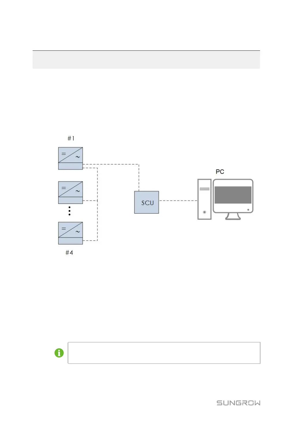
8.1 Communications Diagram
The wiring between the internal devices of the MV grid-connected inverter has been com-
pleted before delivery. Connect the PC with the switch inside the power distribution cabinet
with the CAT-5e cable on site. After that, the WEB interface can be accessed on a PC.
figure 8-1 Wired Communication Diagram
8.2 Preparation Before Login
8.2.1 Login (PC)
Step 1 To connect the PC to the product, connect the network cable to the network port of the PMD
switch.
Step 2 Configure the IP address of the PC. Set the IP address of the PC to the same network seg-
ment as the NET1 address of the smart unit board.
Default IP address of the NET1 port: 12.12.12.12.
Default IP address of the NET2 port: 14.14.14.14.
- - End
 Loading...