59
9
Operation Mode
9.1 Mode Change
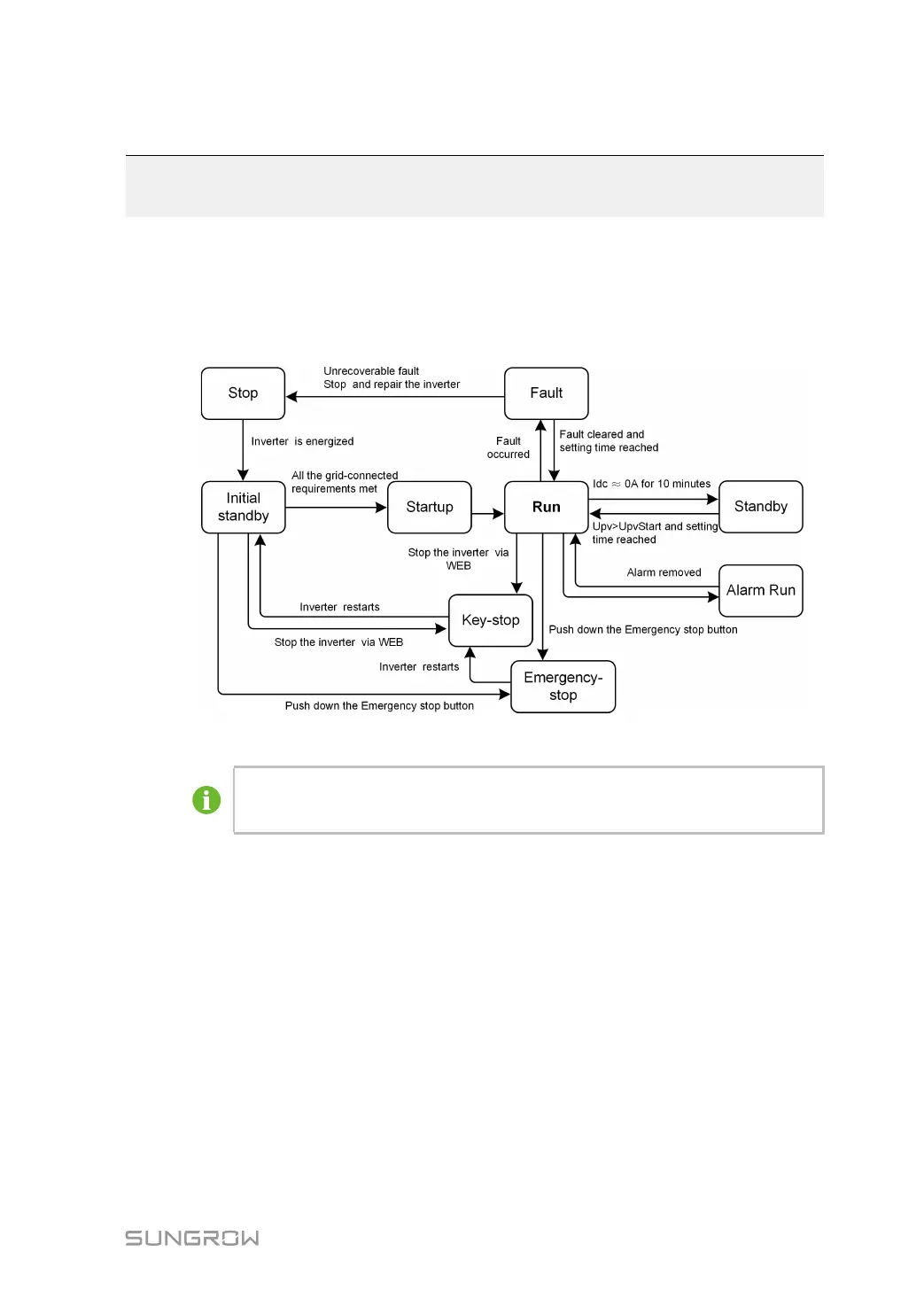
After being energized, the MV Station switch among different modes as shown in the figure
below.
figure 9-1 Operation modes change
U
pv
is the DC input voltage of the PV array.
U
pv
Start is the inverter DC side startup voltage.
9.2 Operation Mode Description
Stop
This is the initial state of the module. The module DC and AC switches are in the “OFF”
position; the upstream and downstream connections are disconnected. The module is
therefore electricity-free.
Initial Standby
When the module upstream and downstream connections are connected and the DC
switches are in the “ON” position, the module turns to the Initial Standby mode.
Module will continuously check if the PV array and the grid meet the grid-connection
requirements. If the module DC input voltage is higher than the module startup voltage and
the startup time is reached, whilst the requirements of the grid side parameter are satisfied,
module will turn from the Initial Standby mode into the Startup mode.
 Loading...