42
Assignment of sensor connection
Pin assignment
of plug sensor
Connection designation
of sensor
Connection designation
of solar inverter
Pin 1 Positive-signal irradiation strength
Solar
Pin 2 Positive-signal temperature
Temp
Pin 3 Reference earth
V-
Pin 4 Positive connection supply +5V
V+
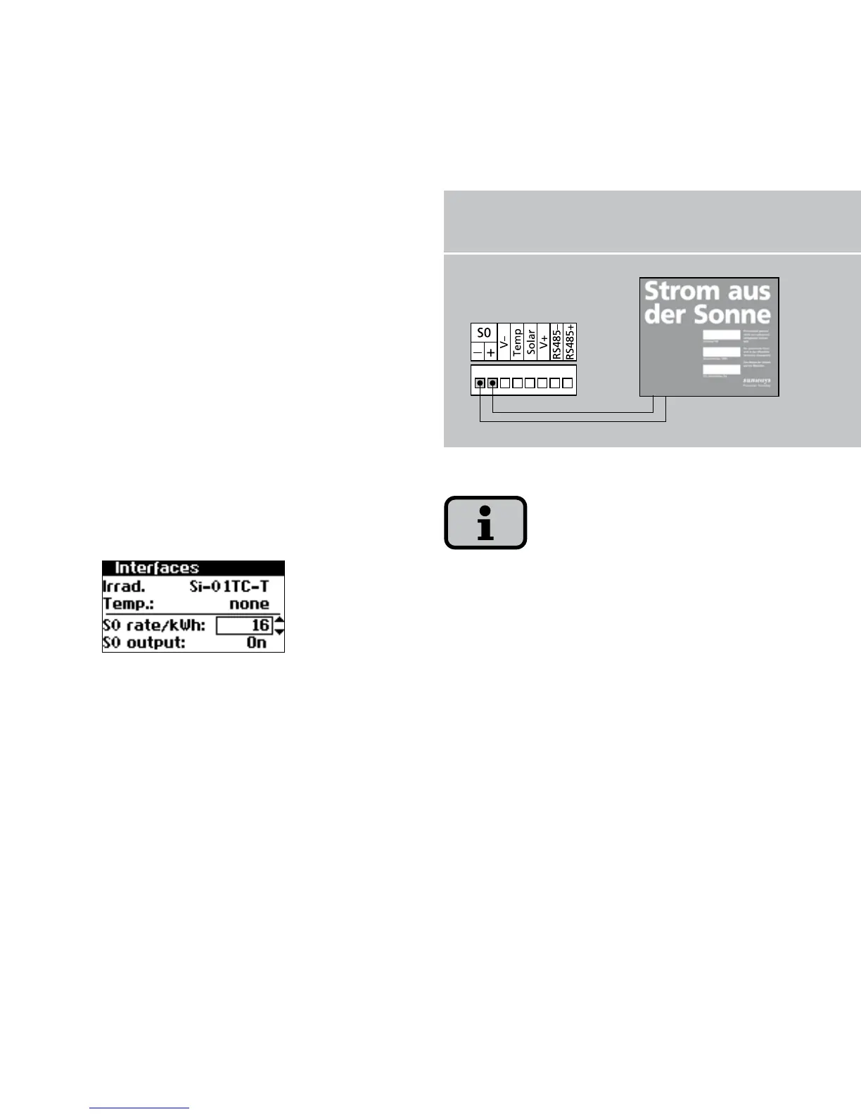
S0 interface
The S0 pulse output enables, for exam
-
ple, the connection of a large display
(Sunways Display) for displaying the
momentary output, the energy yields and
the CO
2
reduction.
You can use the S0 interface on the main
unit if you want to transmit the entire
line yields as a sum to a large display.
The S0 interface is adjusted via the
display on the inverter. Go to the menu
«Settings – Network – Interfaces».
Please note that the maximum pulse rate
may not be greater than 15 pulses/sec.
Calculate the pulse rate depending on
the size of the solar system using the fol
-
lowing formula:
Pulse rate [pulses/kWh] =
50,000/system size [kWp]
The pulse rate must be set on your solar
inverter and on the large display.
S0 interface with large display