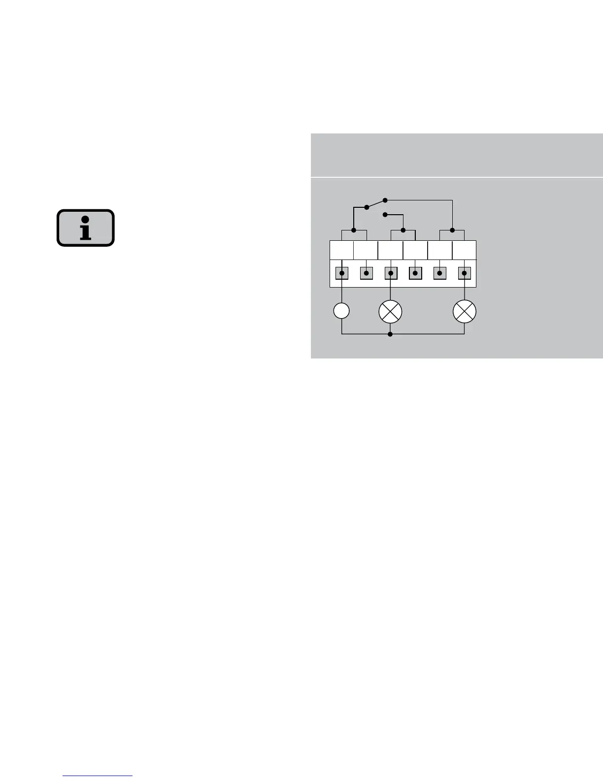
1 Indicator lamp, red
2 Indicator lamp, green
When dimensioning the cross-section,
also take the current consumption of the
connected signalling unit into account!
The solar inverter is supplied by the feed-
in phase from the AC grid. If the feed-in
phase fails, then the alarm relay cannot
switch, although a fault has occurred.