OPERATION OF THE MJB4
16 MJB4 - Operation Rev07 05-10
3
3.1. Definitions
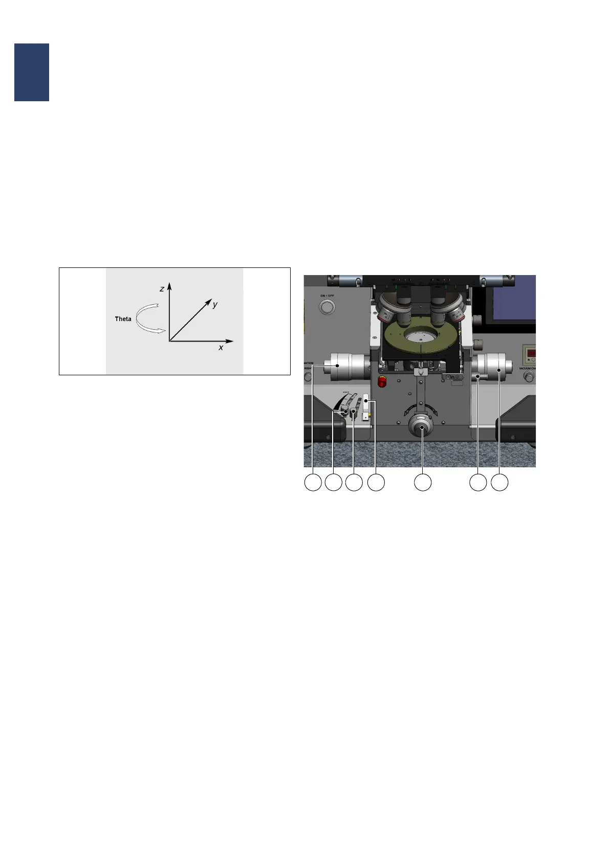
3.1.1. Coordinate System
The unit for position specifications in the X and Y
directions is millimeters. The unit for position
specification in the Z-direction is micrometers. The
specifications refer to a coordinate system whose X
and Y origin is the center of the alignment station.
The zero point of the Z-axis is in the active mask
level or the upper substrate level.
Coordinate system
3.2. Controls and Displays
Main switch with emergency off function
This switch connects or disconnects the mask
aligner and its lamp power supply to or from the
power supply network.
In the event of danger, turn the switch to the OFF
position.
3.2.1. Alignment Stage
Alignment stage with coordinate system
1 Stage – Y motion
2 Separation lever
3 Alignment gap setting
4 Contact lever
5 Variable thickness setting
6 Stage – Theta motion
7 Stage – X motion
Stage - X Motion
This micrometer screw is located on the right side of
the alignment stage and moves the substrate in X-
direction. The travel path is ±5 mm.
Stage - Y Motion
This micrometer screw is located on the left side of
the alignment stage and moves the substrate in Y-
direction. The travel path is ±5 mm.
6
1
2
3
4
5
7