Emission Control Devices: 1B-5
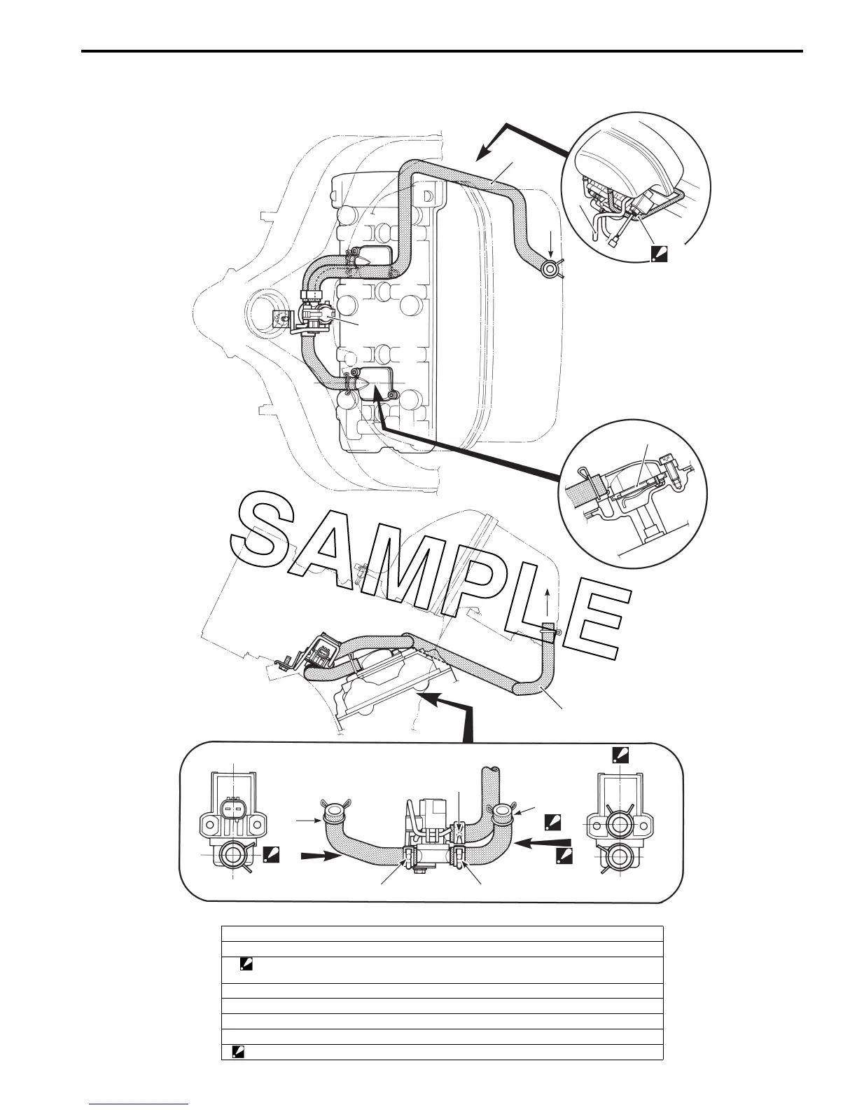
Pair System Hose Routing Diagram
3
4
3
1
2
“C”
3
“A”
“B”
“B”
“A”
“A”
“B”
“D”
“D”
“D”
“D”
I823H1120039-01
1. PAIR control solenoid valve
2. PAIR reed valve
3. PAIR hose (Air inlet)
: Pass the PAIR hose through under the wire harness and front of the PCV hose.
4. PCV hose
“A”: Marking (White)
“B”: Marking (Yellow)
“C”: To the air cleaner box
“D”: The ends of clamp should face each direction as shown in the figure.

 Loading...


