Engine Cooling System: 1F-3
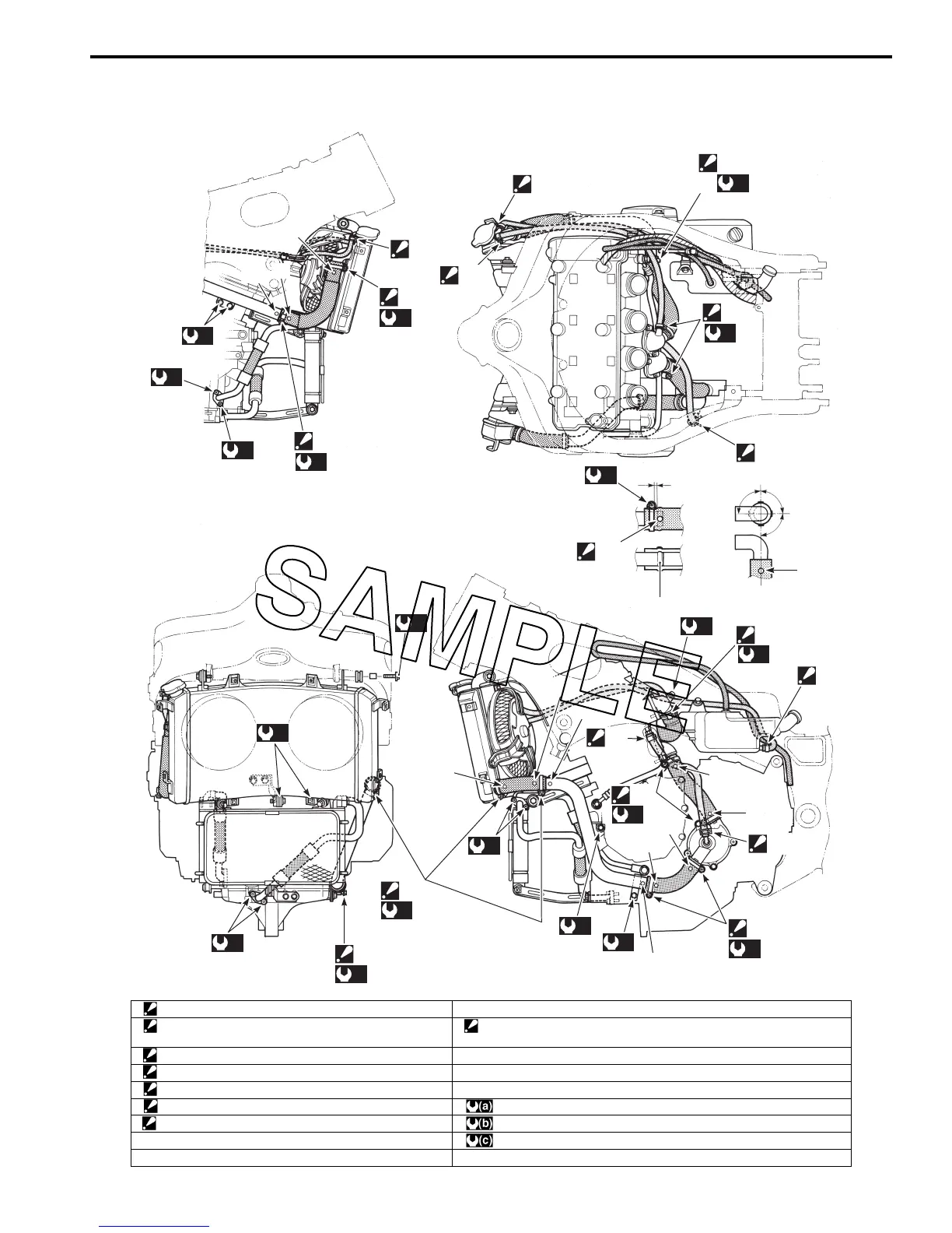
Water Hose Routing Diagram
B823H11602002
(b)
“C”
(c)
“a”
“b”
“a”
“a”
“L”
“F”
(c)
“F”
(c)
(b)
“G”
(c)
(b)
(b)
(b)
“E”
(c)
“I”
“A”
“B”
“A”
“F”
(c)
“H”
“J”
“I”
“G”
(c)
(b)
(b)
“C”
(c)
“K”
“K”
(a)
“E”
(c)
“D”
“I”
“H”
“C”
“I”
“H”
“C”
“J”
(b)
(b)
“H”
“I”
“J”
“F”
(c)
I823H1160002-06
“A”: Clamp ends should face forward. “J”: Punched marking
“B”: Clamp ends should face inside. “K”: Color paint marking position
: Align the marking “K” with rib “L” of pipe.
“C”: Clamp ends should face backward. “L”: Rib of pipe
“D”: Clamp ends should face upside. “a”: 90q
“E”: Clamp screw head should face backward. “b”: Keep a clearance.
“F”: Clamp screw head should face outside. : 6 Nm (0.6 kgf-m, 4.5 lb-ft)
“G”: Clamp screw head should face downside. : 10 Nm (1.0 kgf-m, 7.0 lb-ft)
“H”: Yellow marking : 1.5 Nm (0.15 kgf-m, 1.0 lb-ft)
“I”: White marking

 Loading...