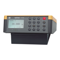
54
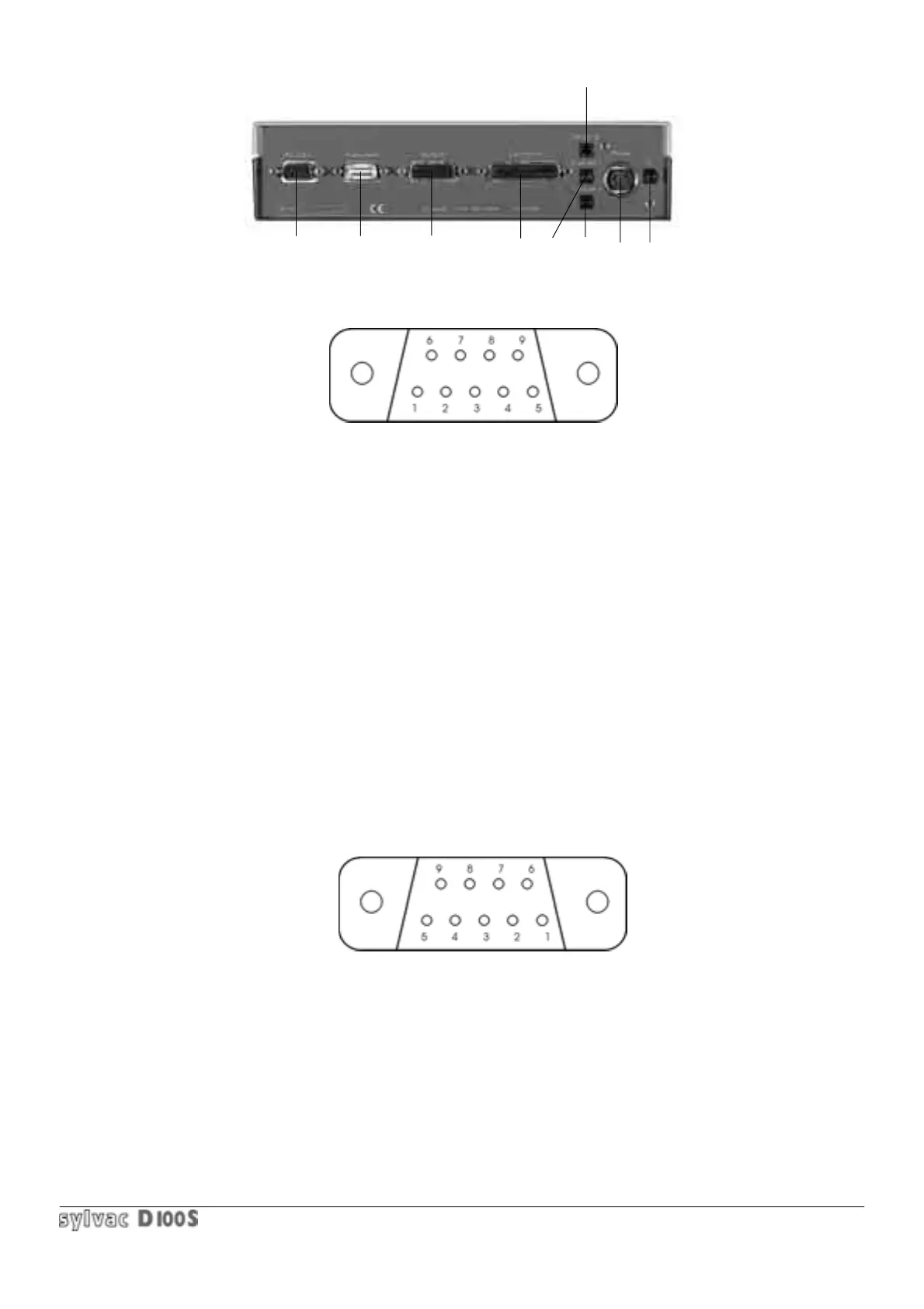
1.8 REAR PANEL
1.8.1 RS-232-C Input/output
9 pin D-sub female connector (external view) :
Pin 1 : Charger output 8.5 V / 300 mA non-regulated (current limit protection). Output only with charger
connected.
Pin 2 : RXD = RS-232-C output when Print key or foot pedal (if configured) is pressed, or by remote
command.
Pin 3 : TXD = RS-232-C input for remote command from computer.
Pin 4 : DTR (Data Terminal Ready) :not used.
Pin 5 : SG (Signal Ground) =Signal ground.
Pin 6 : DSR (Data Set Ready) =not used.
Pin 7,8 : Unconnected.
Pin 9 : 6 à 7 V / 150 mA accumulator output, non-regulated (current limitation).
To configure the RS-232-C transmission parameters, press Setup key then Print key.
(refer to Print key section 1.6.14).
1.8.2 RS-232-C input instrument (Opto-RS simplex or duplex)
9 pin D-sub male connector (external view) :
Pin 1 : Charger output 8.5 V / 300 mA
Pin 2 : TXD = RS-232-C input from connected OptoRS instrument.
Pin 3 : RXD = RS-232-C output for Opto-RS duplex instrument : data request or min/max. mode selection.
Pin 4 : DSR : output for data request for OptoRS simplex instrument or positive supply for OptoRS duplex.
Pin 5 : SG = Signal ground.
1 2
3
467
89
5