56
Notes :
if pneumatic unit is activated, classification is only possible for 2 classes.
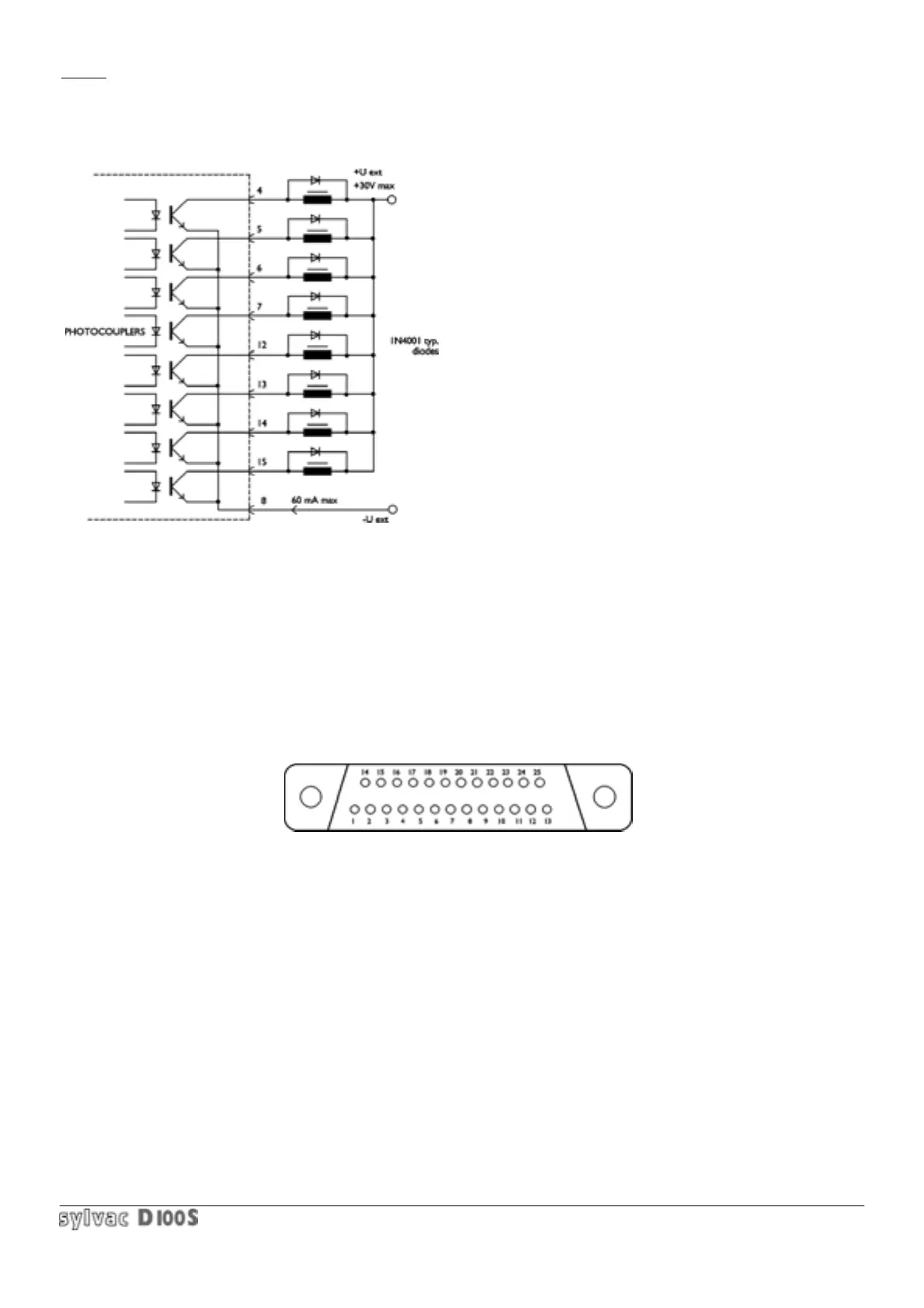
Pin 8 : Common for 8 opto-coupler outputs.
Max voltage = 30 V, max. current = 60 mA per output.
The opto-coupler outputs must be supplied externally
With negative voltage to the common emitters (pin 8)
The protection diode is necessary in the event of
Inductive charge ( électrovalve), relay, solenoid, etc..)
Pin 10 : 8.5 V / 300 mA output, non-regulated (protected), only if charger is fitted).
Pin 11 : 6 to 7 V / 150 mA output, non-regalated (protected)
1.8.4 Centronics Output : parallel printer link
25-pin D-sub female connector (external view) :
Pin 1 : Strobe = output signal which validates data D1 to D8.
Pin 2 to 9 : data outputs D1 to D8.
Pin 11 : Busy = input signal indicating if printer is ready to receive data.
Pin 18 to 25 : signal ground.
Pin 10 and 12 to 17 : not connected.
Link cable : standard PC - printer.