AR 2000 Operator's Manual
67
Chapter 7
Using the Upper Heated Plate
Introduction to the Upper Heated Plate
At the standard AR 2000 Smart Swap™ Peltier plate's temperature range extremes, a temperature gradient may
be introduced across the sample, the significance of which will depend on the sample’s thermomechanical
properties. Although this gradient can be reduced by the use of an upper geometry containing a thermal break,
it can only be effectively eliminated if the Peltier plate and upper geometry are constrained to the same tempera-
ture. The Upper Heated Plate (or UHP) has been developed to allow this and is used in conjunction with the
standard Smart Swap™ Peltier plate.
The Upper Heated Plate consists of
two main components:
• A fixture that attaches to the
rheometer head. This fixture
contains electrical heating
elements and a coolant channel.
• An upper geometry holder that
attaches to the rheometer rotating
shaft. The geometry holder
contains a heat spreader.
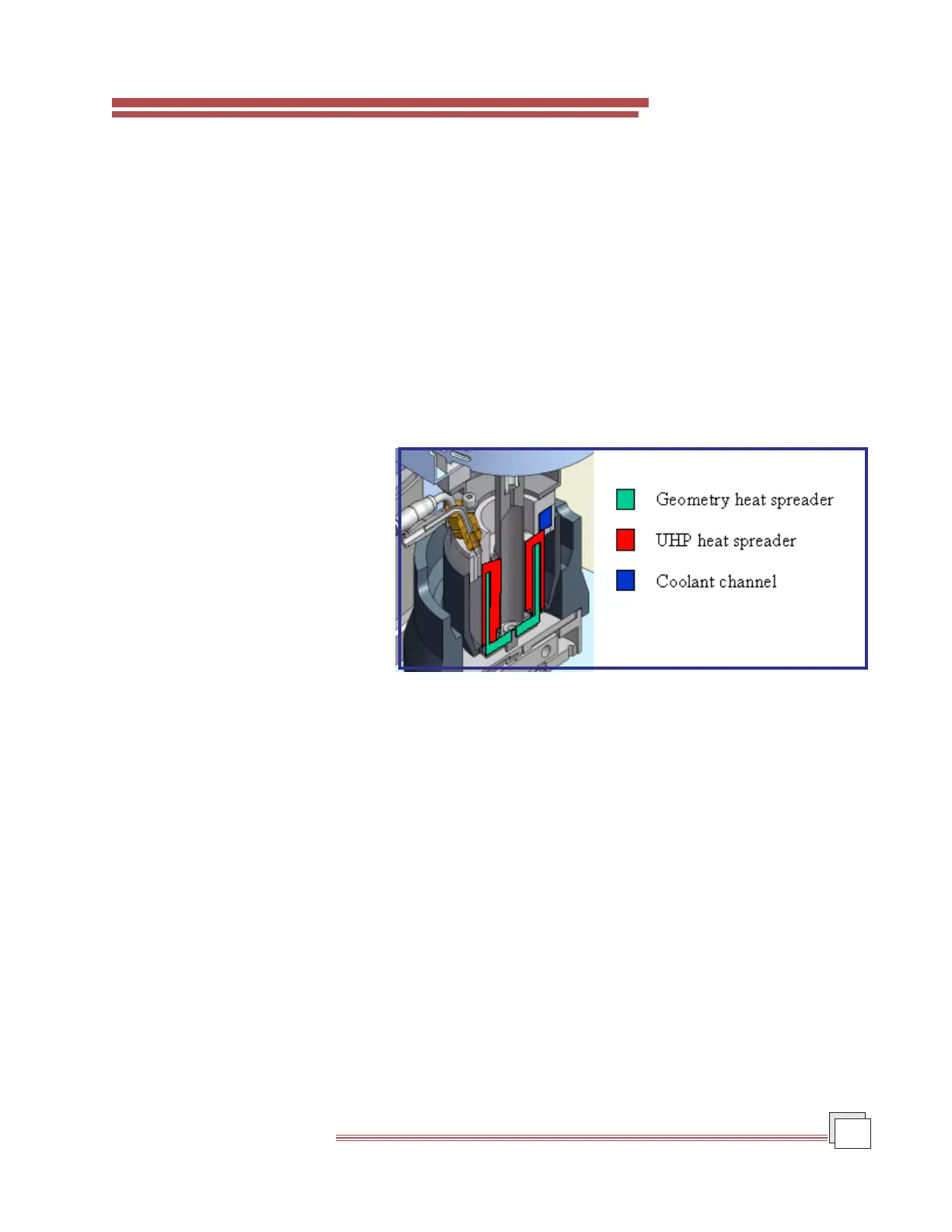
There is no physical contact between
the two components (see Figure 7.1).
Heating of the Upper Heated Plate is
through the electrical elements.
Cooling is provided by vortex air, water, or other fluid carried in the coolant channel.
Control of the water flow is through a 3-way solenoid valve contained in a Cooling Control Unit (CCU) placed
upstream of the Upper Heated Plate. The CCU is also connected to an air supply, allowing purge air to displace
water from the coolant channel during heating or at elevated temperatures. If vortex air or fluids other than
water are used as coolants, purge air is not required, and the CCU is replaced by a 2-way solenoid.
A Pt100 probe placed within the Upper Heated Plate heat spreader reads the temperature of the Upper Heated
Plate. The offset between the read temperature and that of the upper geometry plate is obtained by prior calibra-
tion.
An inert gas atmosphere can be produced using the inert gas inlet located between the inlet and outlet coolant
ports on the Upper Heated Plate. The inert gas jets are located on the underside of the heating element cover. A
protective sample cover and an instrument air bearing clamp are also provided.
Figure 7.1
Exploded View of the UHP and Upper Geometry Holder