AR 2000 Operator’s Manual
87
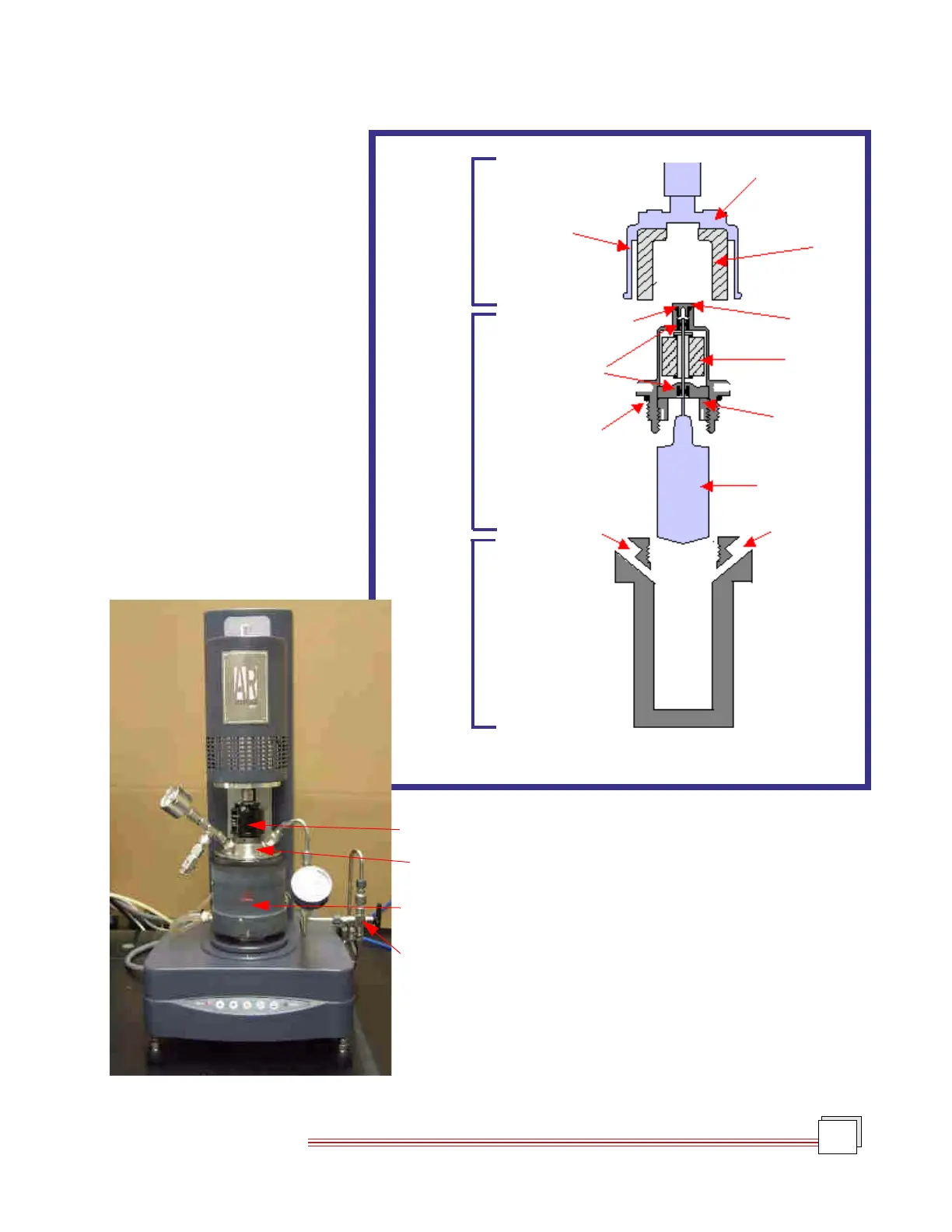
Pressure Cell Components
The Pressure Cell consists of four main
component assemblies. These compo-
nents include the pressure cell cup, the
concentric cylinder rotor, the magnet
assembly, and the pressure manifold.
Figure 8.1 shows a schematic cross sec-
tion of the pressure cell cup, rotor, and
magnet assemblies, and Figure 8.2
shows a fully configured Pressure Cell
installed on an AR Rheometer. The
following section will discuss these
four components individually.
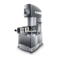
The Pressure Cell is shown assembled on the AR rheom-
eter, with the instrument head in the DOWN position, in
Figure 8.2 to the left.
Magnet
Cup
Peltier
Heating
Jacket
Manifold
Assembly
Figure 8.2
Pressure Cell on AR Rheometer
Cup
Cover
Retaining Plate
Kalrez
TM
Seal
Sapphire
Bearings
Gauge Port
4-Pole
Magnet
Thumbscrew
Locking Nut
Rotor
Inlet Port
Kalrez® Seal
4-Pole
Magnet
Magnet
Assembly
Rotor
Assembly
Figure 8.1
Cross Section Schematic