AR 2000 Operator's Manual
64
Clockwise Counterclockwise
(Anticlockwise)
Figure 6.10
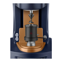
Attaching/Removing A Geometry
Attaching a Geometry
This procedure is carried out using the same
technique as described for the air-bearing
clamp:
1. Switch on the air and remove the air-
bearing clamp by turning the draw rod
counterclockwise (anticlockwise).
2. Push the geometry up the drive shaft and
hold it while placing the draw rod in the
screw thread of the geometry.
3. Screw the draw rod upwards (clockwise).
It should be screwed finger tight, but not
forced.
To remove the geometry, use the reverse
process.