AR 2000 Operator's Manual
115
Experimental Procedure
The calculation of the interfacial viscosity for the general case described previously is complicated, and can only
be solved using numerical procedures [2]. However, if the first order assumption is made that the contributions
from the three phases are independent of each other, the calculation becomes relatively straightforward. The
contributions from each of the two bulk fluids can be obtained separately and the interfacial contribution can be
obtained by subtraction of these from the total contribution.
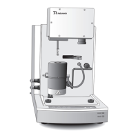
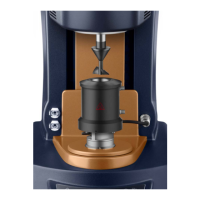
• For this procedure, the cup is filled completely with one of the fluids and the geometry is set to gap of
19,500 µm, so that the disc edge is level with the half full mark.
• The instrument torque is determined over the range of angular velocities (or shear rates) of interest.
• The process is repeated for the other fluid, and the contributions to the torque from each fluid at each
angular velocity are added.
This total will be twice that of the upper and lower fluids combined when they each occupy half the cup
volume, and can therefore be halved and subtracted from the total torque, obtained in the presence of the
interface, to give the contribution due to the interface. A two-dimensional analog of the concentric cylinder
geometry is used to give the interfacial viscosity. Details of the analysis are given below.
Determining Each Fluid's Contribution
Follow the steps below to determine the contribution from each bulk fluid.
1. Make sure the gap is set at 19500 µm.
2. Fill the cup with Sample Fluid A, until the fluid just reaches the lower edge of the groove on top of the cup.
3. Gently lower the lid. The fluid should overflow from the annular gap between the lid and the geometry.
4. Use a Flow procedure to apply the required angular velocity (or shear rate) or range of velocities. Alterna-
tively, apply the required torque or range of torques. It is usually preferable to use a Steady State Flow
procedure for this, but the details will depend on the sample, and the reasons for conducting the experi-
ment. This procedure gives the torque contribution of Fluid A, M
Acalibration
(Ω), at angular velocity Ω.
NOTE: When setting up the procedure, in the Conditioning step on the Settings tab, uncheck the "Wait for
correct temperature" box. Any temperature settings in the procedure will be ignored.
5. After running the procedure, raise the instrument head.
6. Remove, clean and replace the cup.
7. Repeat the procedure for the Sample Fluid B, to obtain M
Bcalibration
(Ω) then remove, clean and replace the
cup.