AR 2000 Operator's Manual
78
Calibration of the Upper Heated Plate
The temperature of the Upper Heated Plate is read from a probe positioned within the Upper Heated Plate heat
spreader as close to the upper geometry as possible, although not in physical contact with it. The temperature of
the Peltier plate is read from a probe positioned in thermal contact with the plate as close to the surface as
possible. The temperature reported by Rheology Advantage is that of the Peltier probe. For best performance the
Upper Heated Plate probe should be calibrated to the temperature of the upper geometry plate.
NOTE: Calibration should be performed on installation of the Upper Heated Plate, and at least
annually thereafter. The calibration routine may take several hours, and it is more efficient to
perform a single calibration with more points, rather than several calibrations with fewer points
NOTE: Le calibrage devrait être effectué sur l’installation de l’Upper Heated Plate, et au moins
annuellement ensuite. La routine de calibrage peut prendre plusieurs heures, et il est plus
efficace d’effectuer un calibrage simple avec plus de points, plutôt que plusieurs calibrages
avec peu de points.
During the automatic calibration routine a heat flow sensor is used to determine the temperature gradient
between the Peltier plate and the upper geometry. The gradient is reduced to within preset tolerances by adjust-
ing the temperature of the Upper Heated Plate while the temperature of the Peltier plate is held constant. After
each adjustment a user-defined stability criterion is applied and, once temperature stability is achieved, com-
parison is made with the gradient tolerance. When the gradient tolerance condition is satisfied the temperature
value is accepted.
The procedure is repeated for a number of points over a range set by the user. When the calibration routine is
complete the temperature values for the upper
geometry determined by the calibration are compared
with those reported by the Upper Heated Plate probe
to obtain the appropriate offset and span values.
1. Under the Options menu click Instrument and
then the Temperature tab. The window, shown
in Figure 7.15 on the previous page, will be
displayed.
2. Ensure that the Cooling temperature and Cool-
ing range boxes contain the appropriate values.
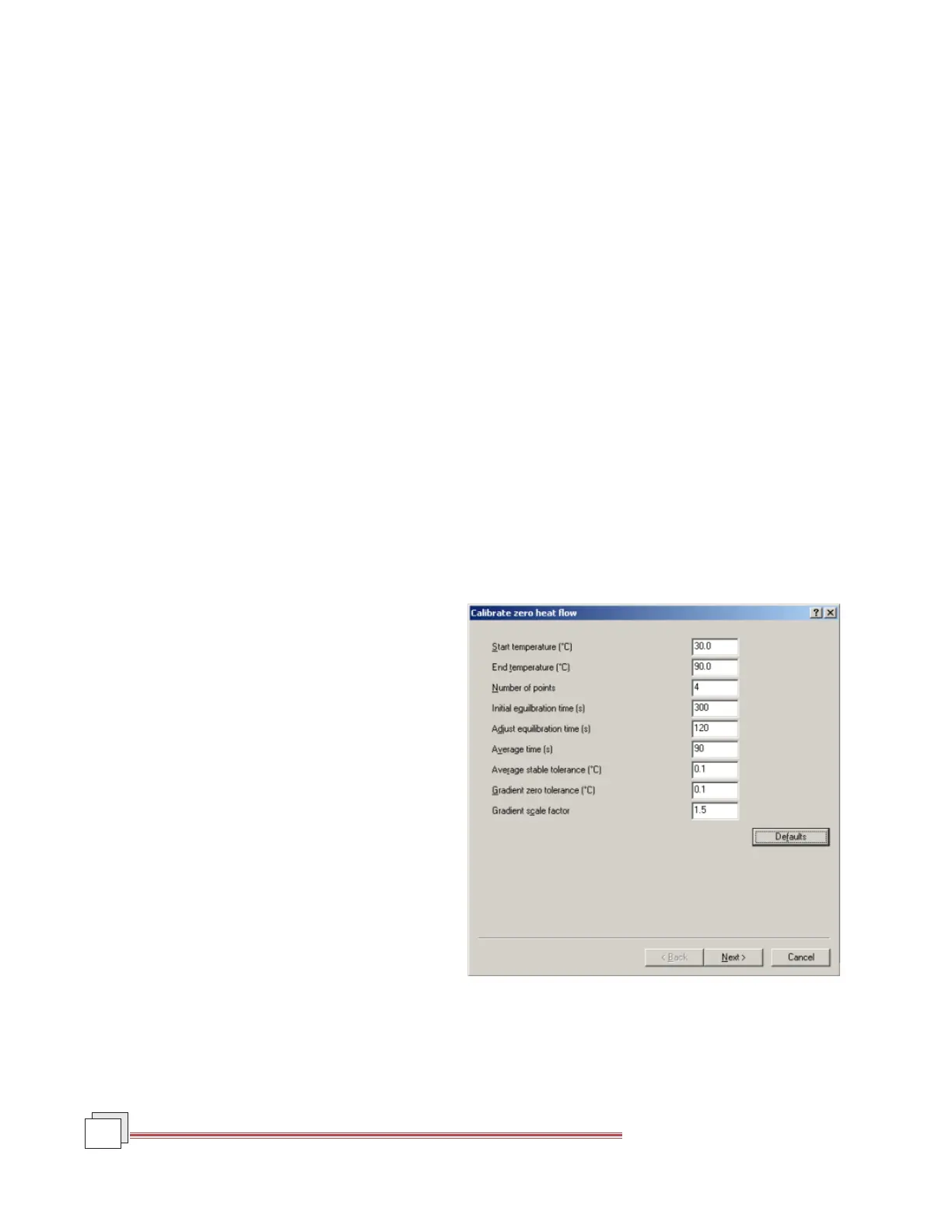
3. Click Calibrate. The Calibrate Zero Heat Flow
window, shown in Figure 7.16 shown to the
right, will be displayed.
The parameters shown on the window are
described as follows:
• Start Temperature: Temperature at which
calibration is to begin.
• End Temperature: Temperature at which
calibration is to end.
• Number of Points: Number of temperature points, which will be at equal intervals.
Figure 7.16
UHP Calibrate Zero Heat Flow Window