RSA-G2 Getting Started Guide Page 19
CAUTION: Force Rebalance Transducers contain a precision air bearing that is equipped with a
bearing lock, which prevents movement of the air bearing when no air is applied. To avoid damaging
your transducer, familiarize yourself with the operation of the bearing lock, and read the instruc-
tions carefully.
MISE EN GARDE: Les transducteurs de rééquilibrage de force contiennent un palier à air de préci-
sion équipé d'un verrou de palier qui empêchent le mouvement du palier à air lorsque l'air n'est pas
appliqué. Pour éviter d'endommager le transducteur, familiarisez-vous avec l'utilisation du verrou
de palier et lisez attentivement les instructions.
The FRT consists of an axial (normal force) servo control system. This system utilizes position feedback to
maintain the axial FRT shaft in a null position all the time. When an axial force is applied to the FRT shaft,
the servo control system responds by driving the required current through the axial force motor coil to
maintain the shaft null position. The electrical current required to maintain this null position is proportional
to the amount of axial force applied to the shaft. The current is converted to a voltage through a precision
current sense resistor, and the voltage is measured and scaled to provide a force value. Selection and
control of the force range is performed using the TRIOS software. Note that the maximum force
measurable by the transducer is 3500 grams.
For axial force, full-scale measurements can be made in both the upward and downward directions. The
weight of the shaft and tool does not reduce the measurement range in the downward direction.
The actuators (motor and transducer) contain a precision air bearing that is equipped with a bearing lock,
which prevents movement of the air bearing when no air is applied. To avoid damaging your motor or
transducer, familiarize yourself with the operation of the bearing lock and observe the following cautions:
• Do not unlock the bearing unless air is applied to the actuators.
• If the instrument will be moved or the air supply removed for an extended period of time, lock the
actuators prior to removing air.
• If the air supply is interrupted while the actuators are unlocked, do not touch the anvil until air is
restored.
• Maintain airflow to the actuators at all times to prevent contamination of the air bearing.
Failure to observe these cautions will result in damage to the actuators.
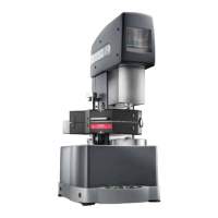
Linear Air Bearing Motor
The linear air bearing motor, also referred to as the actuator, deforms the sample by applying an axial
strain to the sample. The motor combined with the step motor can be operated in dynamic (sinusoidal)
mode or step strain and creep-recovery tests.
Figure 8 RSA-G2 linear air bearing motor.