RSA-G2 Getting Started Guide Page 62
Installing the Lower Geometry
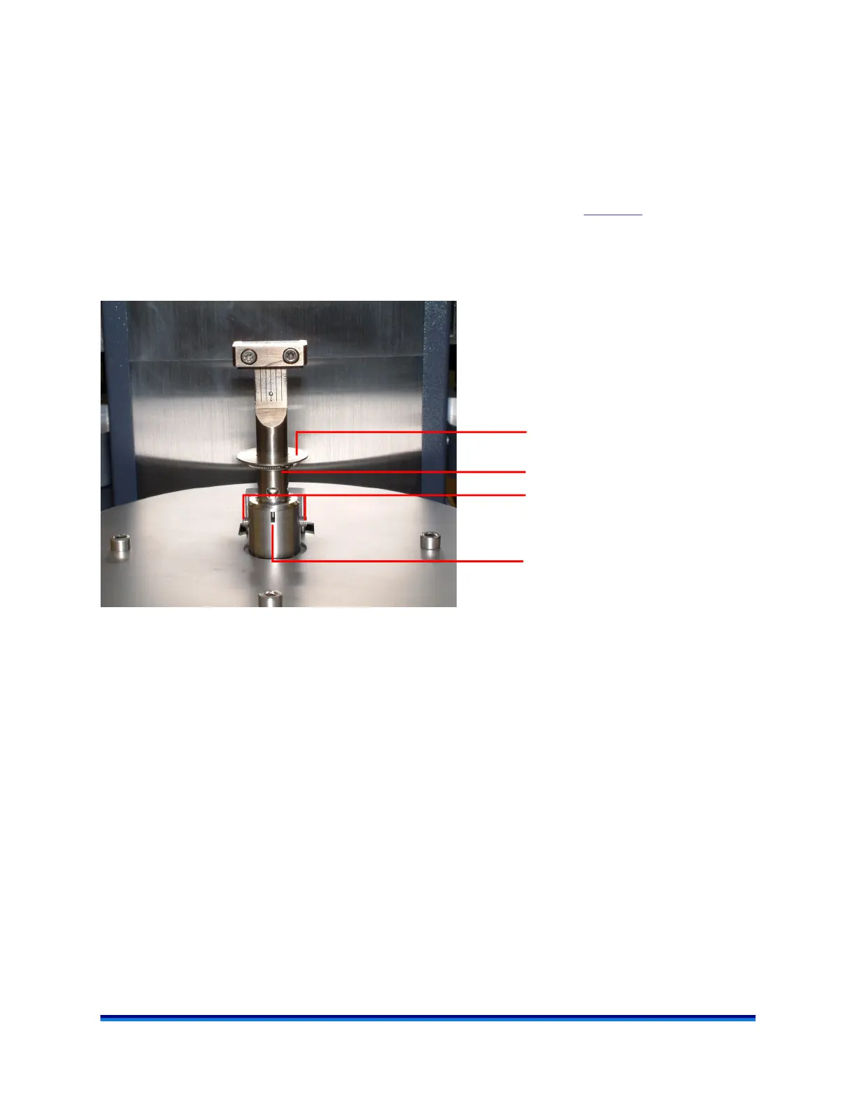
Follow the directions below to install the lower geometry on the motor.
1 Loosen the set screws on the transducer mount using the Allen wrench supplied in the geometry kit.
2 Obtain the desired geometry. Make sure there is no dirt or dust at the location surfaces for parallel and
concentric alignment. Holding the geometry by the shaft, align the notch on the geometry with the slot
on the motor mount and insert the geometry into the motor mount. Refer to Figure 37
for notch and slot
locations.
3 Tighten both set screws. The set screw head will move inward to hold the geometry in place. See the
figure below.
Figure 37 Lower geometry installed on RSA-G2.
Geometry shaft
Notch aligned properly in slot
Set screws
Geometry baffle