RSA-G2 Getting Started Guide Page 20
Motor position is recorded using an LVDT feedback servo system. Frequency range is to 100 Hz, ampli-
tude range to +
1.5 mm.
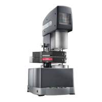
Bearing Lock
The motor and transducer each are equipped with a bearing lock to protect the delicate air bearings during
shipping, and any other times when air cannot be supplied to the instrument. Retain the locks in case the
test station needs to be moved, or in the event that the air supply will be removed for an extended period of
time. Note that the motor cover must be removed to expose the threaded hole that is used to install the
motor bearing lock.
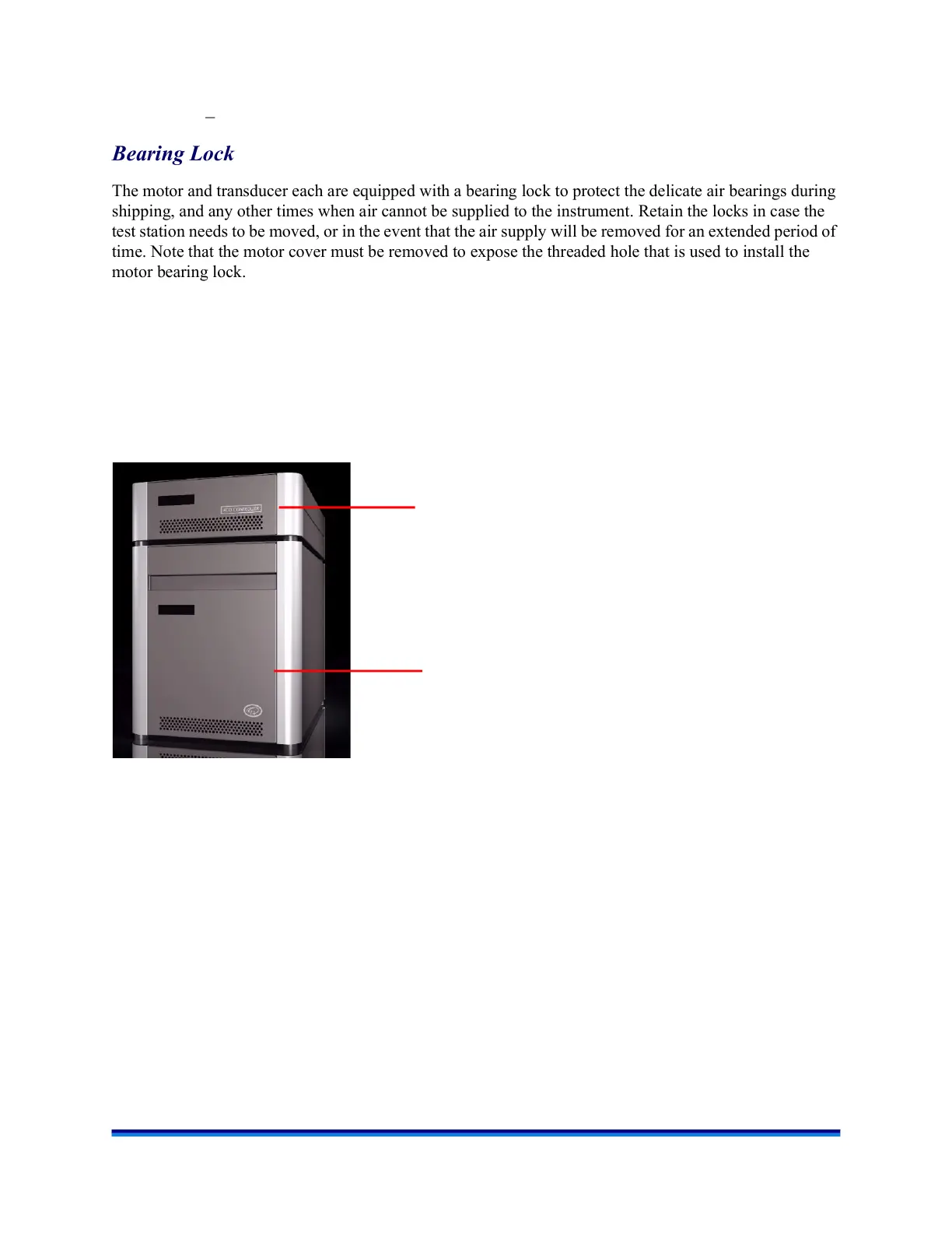
Modular Power Supplies
The RSA-G2 uses a separate box that houses the instrument power supplies, controller, and a self-
diagnostic display.
These stackable units are designed to sit on the floor, under your lab bench, leaving more room on the top
of the bench for other uses.
Figure 9 Stackable power supplies.
FCO Controller power supply
Test station power supply