DISASSEMBLY AND ASSEMBLY
HYDRAULIC PUMP
7
4
HYDRAULIC PUMP 4I0AY001
12. Insert the two cap screws (M10×50) for temporary
assembly into the proper positions on the top side
and loosely tighten them down. Once the gap be-
tween the joining surfaces reaches 10 mm (0.39 in.),
insert the cap screws (M10×40) into the remaining
two screw positions and tighten them down.
13. Take out the cap screws for temporary assembly and
replace them with the cap screws (M10×40), and
tighten those screws down to secure the parts in
place.
Cap screws: 51.0 to 64.7 N·m (37.6 to 47.7 ft.-lb)
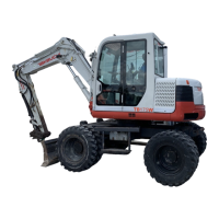
14. Attach the collar (40) and the coupling (39) to the
gear pump linking section of the piston pump and
then attach the O-rings (42) and (44).
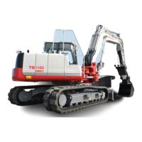
15. Attach the gear pump using the two cap screws (1)
and two washers.
Cap screws: 19.6 to 23.5 N·m (14.5 to 15.2 ft.-lb)
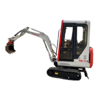
16. To check to see if the assembly is in order, turn the
pump while holding the shaft in place loosely using a
vise. If it does not rotate smoothly, take the assembly
apart and try again.
 Loading...