User manual 3-3
DSC/DSCT Series
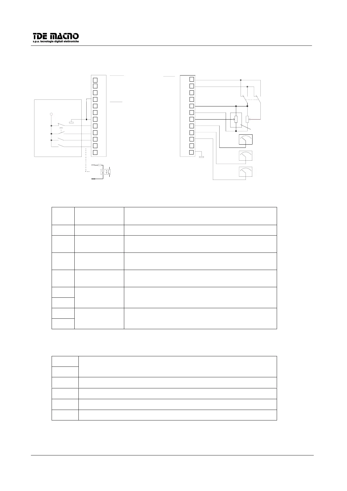
3.3. DEFAULT CONNECTIONS
J1
10
11
12
2
3
4
5
6
7
8
9
1
L.O.2
L.O.2
+24V
0VP
L.O.1
L.O.1
L.I.C
L.I.5
L.I.4
L.I.3
L.I.2
L.I.1
+24V
0
PLC o CNC
0V
0V
0V
A.P.O.
IOUT
TG.O
I.LIM
+10V
T.REF
S.REF
S.REF
0V
J2
0V
(
∗
∗∗
∗
)
(
∗
) If used it will be enabled with c31
10K
10
11
12
2
3
4
5
6
7
8
9
1
CW/CCW
1-2-3-4-5
6
Meaning and programming of digital I/O defaults (connector J1):
L.I.1 Torque enable Enables the drive to work with external torque reference
signal T.REF(±10V)
L.I.2 Run Enables the power to the motor.
L.I.3 Reference 1
enable
Enables the speed reference present in S.REF and
S.REF/.
L.I.4 Alarm reset Resets the alarms if the alarm causes have been
removed (minimum time of transition T=100mS).
L.I.5 External enable If this input is in the LOW state, the drive is in alarm A8,
and is not ready. (External emergency)
L.O.1
L.O.1/
Drive ready Active when the drive is ready to run (no alarm
presence).
L.O.2
L.O.2/
Drive running Active when the drive is running.
Meaning of the analog signals (connector J2):
S.REF
S.REF/
Differential speed reference input ±10V
I.LIM
Maximum current limit 0÷ +10V
TG.O
Actual speed output -10V ÷ +10V
IOUT
Torque current request output -10V ÷ +10V
A.P.O. configurable analogic output.
Note: L.I.1
÷
÷÷
÷
L.I.5 are comanded by signals between the range of 18V
÷
÷÷
÷
27V.


 To Next Page