User manual 13-1
DSC/DSCT Series
13. POSITIONER
13.1. USE OF THE BRUSHLESS MOTOR DRIVE AS POSITIONER
The drive can be used in point to point positioner function with a maximum of two different movements,
unless it is continuously modified by the serial line. For the modality of the positioner the following
parameters are active in this way:
P01, P02, P03, P07, P08, P09, P10
and the following software switches:
c26, c35, c36, c37, c38, c40
. The numbers to be set,
P07
and
P08
,
are given in
pulses within a
maximum
number of
19999, referring to the pulses/rev elettr. resolver number chosen in
c11
(with the use of the serial
line the maximum limit of run raises to ±32750 pulses)..
The sign of the movement number imposed defines the movement direction independent of the speed sign;
Positive sign
= CW movement (speed
d5
≥0)
Negative sign
= CCW movement (speed
d5
≤0)
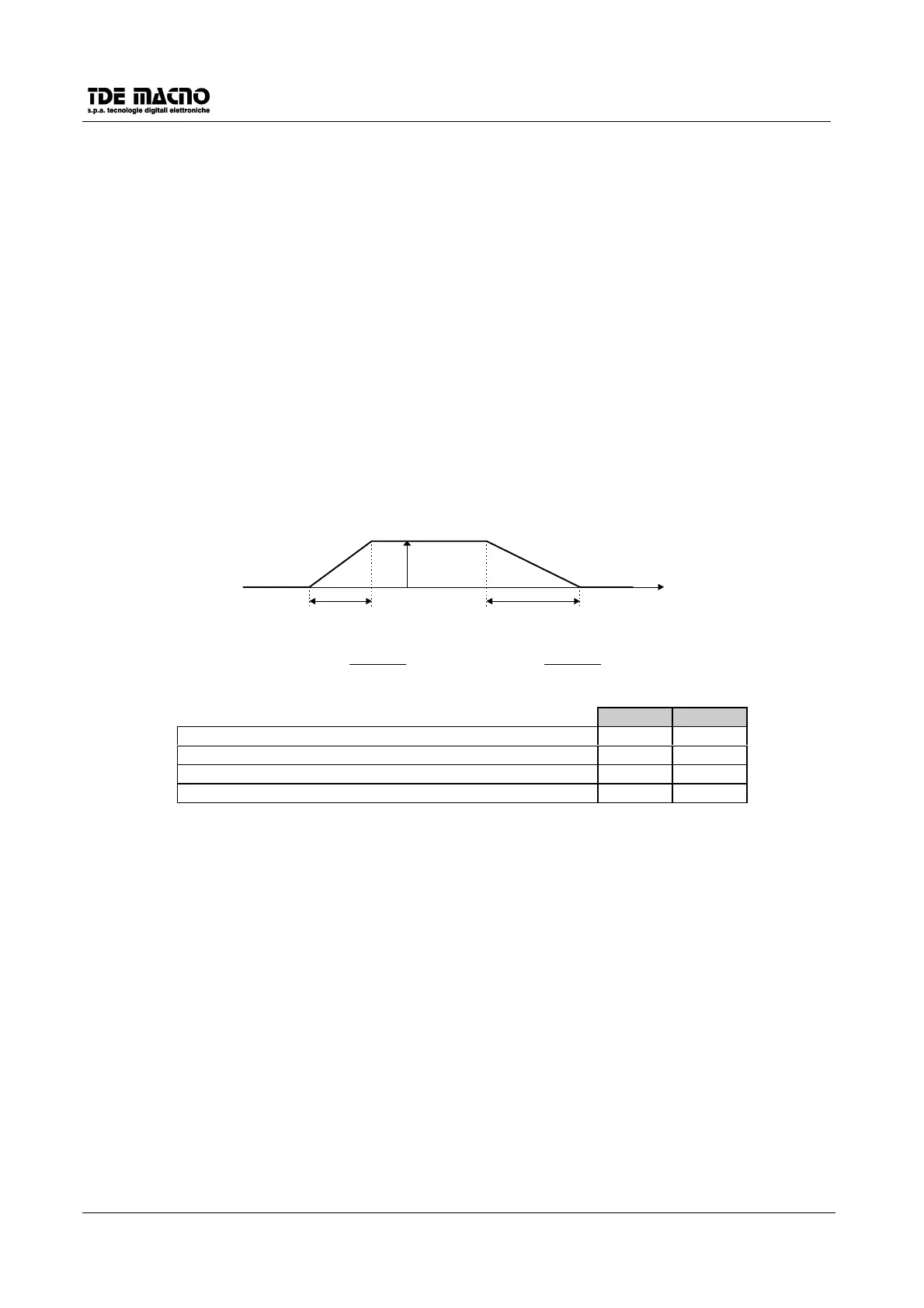
For the maximum speed and the acceleration and deceleration times are used the same parameters as the
speed regulator; in particular with reference to the figure below for the two movements the parameters in the
table are used.
Taccpos Tdecpos
Vmaxpos
t
TT
V
accpos acc
maxpos
=
%
100
TT
V
decpos dec
maxpos
=
%
100
Pos. 1 Pos. 2
Displacement number in encoder pulses P07 P08
Max displacement speed in % of P52 P01 P02
Acceleration time up to Vmaxmotor P52 P11 P13
Deceleration time from Vmaxmotor P52 P12 P14
The positioner mode can be selected via software setting connection
c35
=1 (by default
c35
=0) or via
hardware by means of one of the logic inputs, after it has been configured by means of
c1
,
c3
,
c4
or
c5
and
enabling the ramp connection
c26
=1.
The movement starts on the rise front of one of the programmed inputs. This start signal can be given also
while a positioning is in course, but it must be kept in logic state H until the actual positioning has terminated.
The following programming possibilities have thus been added to the logic inputs:
The displacement numbers (
P07
,
P08
) can also be changed during the movement by means of the serial
line, and are accepted at the first stop, after the stop in position signal. Because of this, once all the
parameters for the two movements are set, the serial line can be used to obtain changes in number, leaving
the other parameters unaltered (the average time between two movements started by a serial command is
nearly of 15ms).
The brushless drive with resolver intrinsically contains one absolute number in the arc of an electrical
rotation of the resolver itself; normally however the size of the displacement required is much greater than
one revolution so that in systems where positionings are to be made with reference to an absolute number a
suitable sensor must be placed on the whole travel which, once reached by the motor, allows the system to
know its position. Given that normally the precision or repetivity of the sensors is not sufficient the system
does not consider the sensor as ‘zero’, but considers as zero reference the ‘zero’ number of the resolver
revolution from the side of the direction of movement towards which the motor is sent to look for the sensor
(
c38
=0 search in CCW rotation,
c38
=1 search in CW rotation).


 To Next Page