User manual 11-3
DSC/DSCT Series
11.4.1. STOP IN PLACE
This function is enabled by keeping the motor on-line with digital reference zero; this can be done in two
ways:
1) set
P03
=0 (JOG3=0) and at the same time remove REF1EN and REF2EN (or
c22
and
c23
if used)
2) use LS1 and LS2 opening both contacts after programming both
c24
and
c25
to 1 (default values).
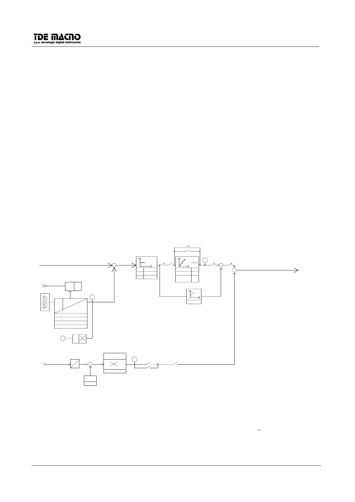
11.5. SPEED REGULATOR AND CURRENT LIMITS
The speed regulator receives the reference from the reference block, and reads the speed feedback from the
resolver connected to the motor shaft. The maximum speed in r.p.m. is set in parameter
P52.
You can have an analog picture of the speed with base scale ±10V at output TG OUT (terminal 5 of
connector J2).
The drive has three working modes:
1. Speed control
2. Speed + torque control
3. Torque control
The input TQ ENABLE select between modes 1 and 3: the drive works in "Speed control" mode if TQ
ENABLE = L otherwise if TQ ENABLE=H (input active) the whole speed stage is excluded and the system
works with the external torque reference signal (analog input TQREF, terminal 9 of connector J2).
P31
(±100.0%) can eliminate the offset and
P32
(±400.0%) is a multiplicative coefficient.
RESOLVER FEEDBACK
SPEED REFERENCE
DR.ON-LINE
+
+
TQ.EN
+
+
P22
P24
P27
Ti=Ta
Kp
C27
D6
C27LIM
Ta (V=0)
Ta(V>VO)
INTEGR.
IN. VAL.
2xVO
KP V=0
KP V>VO
KP
C20
RDC
P20
P21
P23
P88
D4
DAC
RDT
J4
TG.OJ2-5
P52 RPM
P53 motor poles
P54 resolver poles
P55 resolver phase
D5 P52
SPEED REGULATOR
TF
P25=TF
DR. ON-LINEC32
TQ.EN.
D7
CORRECTIVE
COEFFICENT
P32
OFFSET
P31
D
+
-
J2-9 T.REF
A
EXTERNAL TORQUE REFERENCE
-
+
The SPEED REGULATOR is a standard PI (Proportional-integral) with a first-order filter on the speed error.
Parameter settings are possible for the proportional gain Kp, the advance constant Ta (equal to the
integration time multiplied by Kp ) and the filter time constant Tf. Two values can be set for the parameters,
one valid for |speed|+|reference|=0 (
P21
,
P22
) and one valid for |speed|+|reference|>
P20
(
P23
,
P24
); in the
range between 0 and
P20
the system practices a linear interpolation function of the |speed|+|reference|
between the set parameters.
 Loading...