User manual 13-2
DSC/DSCT Series
13.2. ZERO-POSITION SEARCH
Sometimes the machine where the drive is mounted should execute movements refferred to a reference
position (Zero-position). For these cases is provided in the drive an automatic "Zero-position search"
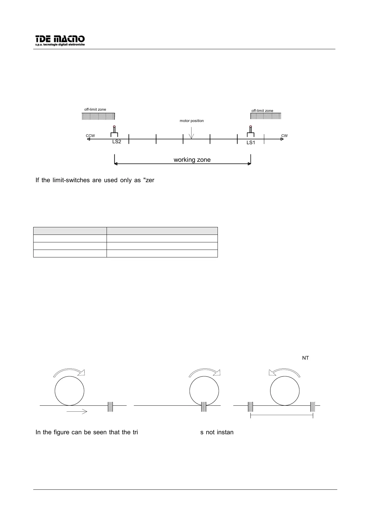
procedure. This procedure is suited for machines moving in a "working zone" between two "off-limits zones"
by limit-switches :
working zone
LS2
LS1
CCW CW
motor position
off-limit zone
off-limit zone
If the limit-switches are used only as "zero-position sensor" for the "zero-position search" procedure, they
must be connected to the drive only during this procedure, and then disconnected from the drive in the
normal working. This can happen in a circular-movement machine: a machine without off-limit zones.
If
c38=0
the search direction is CCW and the "zero-position sensor" is LS2. If
c38=1
the search direction is
CW and the "zero-position sensor" is LS1. The motor must be initially in the working zone.
The "zero-position search" procedure is as following:
Parameter settings description
P03 search speed (% of P52)
P09 displacement offset (enc. pul.)
c38 search direction
1. Start the procedure.
2. The motor moves in the direction specified by c38 at speed specified by P03 versus the extermity of the
working zone. The sign of P03 is not considered, because the direction is determined only by c38.
3. The motor is triggered by a limit-switch and stops.
4. The motor moves in the opposite direction (versus the working zone) until the offset position (set in P09)
is reached. This offset is used to move the motor to a zero position lying in the working zone.
5. The absolute position counter of the drive (displayed in d13) is thus set to zero and the procedure is
complete.
In the "trigger" in the phase 3 can be :
• A limit-switch (LS1 or LS2, depends on the search direction).
• c24= 0 or c25=0, depends on the search direction.
"trigger" position
SEARCH
"trigger" position
"trigger" position
Zero Pos.
offset P09
"TRIGGERING" OFFSET DISPLACEMENT
In the figure can be seen that the trigger of a limit-switch is not instantaneous: between the trigger and his
acquisition by the drive can lap a few milliseconds. So the motor stops in an unspecified point in the
shadowed zone, and the offset displacement (offset P09) can be uncertain.
 Loading...