User manual 6-3
DSC/DSCT Series
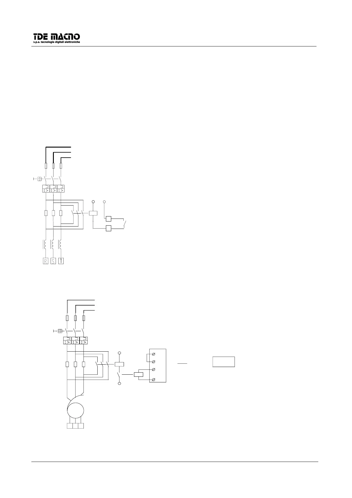
6.4. CONNECTION WITH SOFT-START CIRCUIT
The DSCT drives till the size of 28A have an incorporated device that limits the insertion current. That kind of
device is constituted from a resistor applied after the bridge rectifier and before the capacitors, and from a
relay that short-closes when the capacitors have been completely charged from the network voltage.
For the sizes DSCT-37 and DSCT-47 it’s provided only the relay whose contact (terminals IC) closes when
the capacitors have been charged and the drive is ready to run. That contact must be used together with a
contactor and with three resistors to limit the insertion current; the contact is adaptable to open a voltage of
250Vac with a power of 2.5KVA.
Soft-start circuit for DSCT drive:
R
S
T
K1
R
Va
IC
IC
NOTE:
ITHE VALUE OF R (OHM) FOR THE DIFFERENT SIZES
MUST BE GREATER THAN THE CLAMPING LOAD
RESISTOR
3x380V
THE RESISTANCE POWER DEPENDS ON THE SIZE AND IN ANY CASE
IT SHALL BE CHOSED WITH A POWER :
(In = RATED CURRENT)
P(W) > 5
∗
In
Soft-start circuit for DSC drive:
R
S
T
FUSE SIZING:
THE SIZE IS CALCULATED BY MULTIPLYING THE RATED CURRENT
OF THE AUTOTRASFORMER OR TRANSFORMER BY A COEFFICIENT
JUST GREATER THAN 1
J1
K1
R
Va
+24VP
L.O.1
L.O.1
10
7
8
C7=0
0PV9
Va
K2
(K2 24V < 30mA)
3x220V
T
S
R
NOTE:
PROGRAMMABLE OUTPUT LO1, PROGRAMMED W ITH C7=0 (SECTION
7.3), CLOSES RELAY K1 W ITH A DELAY OF ABOUT 2 SECONDS AFTER
THE SW ITCHING ON OF THE DRIVE.
THE VALUE OF R (OHM) FOR THE DIFFERENT SIZES MUST BE
GREATER THAN THE CLAMPING LOAD RESISTOR, SHOW N IN THE
TABLE AS R-LOAD. THE RESISTOR POWER DEPENDS ON THE SIZE OF
THE DRIVE AND, IN ANY CASE, SHALL BE CHOSEN W ITH A POWER:
P(W) > 5
∗
In
(In = RATED CURRENT)
 Loading...