User manual 11-5
DSC/DSCT Series
The purpose of which is to limit this value within the lowest level of all the following values :
-
parameters
P35
and
P36
-
the analog signal at input J2,6 (I lim) corrected if necessary with
P33
and
P34
if the external limit is
enabled
c31
=1 and EXT.LIMIT=H; this circuit is normally excluded ( default
c31
=0).
-
the value given by the peak current limitation circuit
-
the value given by the motor thermal protection circuit.
Parameters
P35
and
P36
have a regulation range 0-100.0% of the maximum value (limit current) and can
independently limit the torque value required in the two directions of rotation CW, CCW.
The external limitation signal (I lim) must be a positive analogue signal between 0 and 10 V from which an
offset value
P33
(±100%) can be subtracted and which can then be multiplied by the value of parameter
P34
(field ±400.0%)/100 before making it the current limit in both the CW and CCW direction.
The maximum current is limited within curve
TI
⋅
max
compatible with the safety of the semiconductors. In
particular an integration I*t is made and when this value tends to exceed the maximum allowed, which is a
function of the working frequency, the maximum current level which can be required is reduced to a little
more than the rated drive current.
The value curve is such that with motor stopped the overload of twice the rated current
In can be maintained
for about 0.1 sec., when the motor turns at a number of revs corresponding to a frequency greater than
2.5Hz (revs which depend on the number of poles of motor
P53
) this value can be maintained for 2.5sec;
frequencies between 0 and 2.5Hz have intermediate values.
The motor current regulation is of traditional type with PWM with however adaptation of the gain to optimise
the response as a function of the motor features; to obtain this insert the product of the motor phase-phase
inductance value in mH multiplied by the motor rated current as parameter
P58
.
An approximate compensation of the loop response delay is provided by advancing the resolver phase as a
function of the speed.
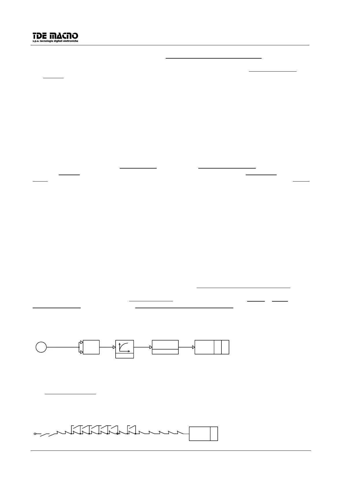
11.7. THERMAL MOTOR PROTECTION
The motor protection circuit acts by calculating the square of the value of the current absorbed by the motor
and integrating it over time according to the motor thermal constant. The result is a value which simulates
the heating in the motor windings, which must not exceed the maximum allowed value, otherwise alarm
A6
becomes active.
For circuit operation the motor current value must thus be set in ratio to the rated drive
P56
(0-100%) and the
value in seconds of the motor thermal constant
P57
(10-600 sec.).
Circuit operation causes the drive to stop immediately deactivating DR.READY if
c34
=1; if
c34
=0 it allows
continuation of the drive operation, but however of the maximum current limit is reduced to the motor rated
current until the temperature is below the limits allowed.
X
THERMAL MOTOR PROTECT A6=H
2
010
6
THERMAL
ALARM
I
rif
I
rif
REFERENCE
OF CURRENT
D11
P57=T
µ
P56=Inom mot
T
>
P56
2
11.8. LOGIC SEQUENCES
The on line ready active condition, or
o9
=H, occurs when no alarm appears and the external enabling and
the enabling via software, or
c29
=1 are present.
RUN
RUN
C29
B.
EXTERNAL
1
2
3
READY RUNNING O9=H
O9
14
13
12
11
10
9
8
7
6
5
4
C34
C19C19C19
12 4
C19
8
+
C19
16