User manual 5-3
DSC/DSCT Series
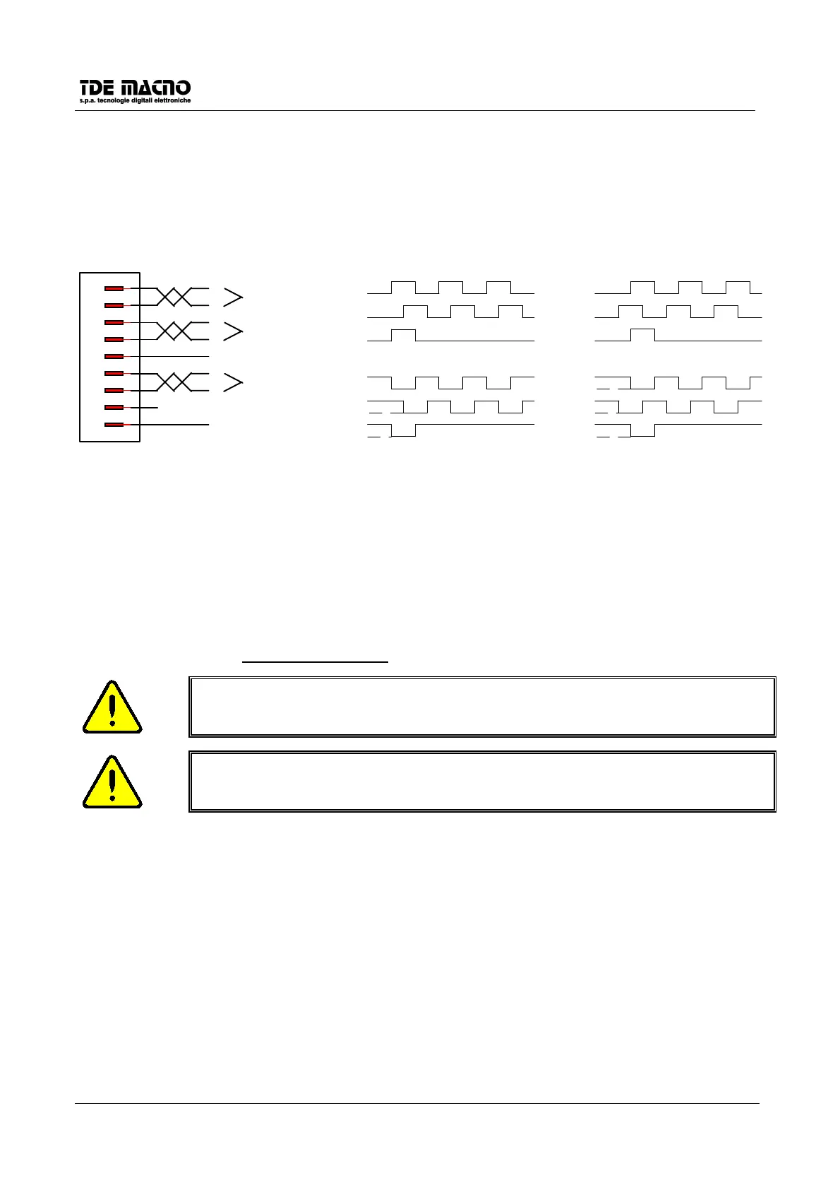
5.4. SIGNALS ENCODER EMULATION (CONNECTOR J3)
The frequency of the signals depends on the motor revolutions, the number of resolver poles and the
selection made (see connection
c10, c11 and c12
) and their behaviour in time depends on the tachometer
signal and on
c10
as shown in the figures below
MALE DB9 CONNECTOR
J3
d5>0 con c10=0
d5<0 con c10=1
d5>0 con c10=1
d5<0 con c10=0
1
2
3
4
5
6
7
8
9
/B
B
/A
A
VS (+)
/C
C
0VS
CHANNEL B
CHANNEL A
CHANNEL C
+VS
0VS
+VS
A
B
0VS
+VS
+VS
0VS
C
0VS
+VS
0VS
*A
*B
+VS
0VS
*C
+VS
0VS
A
+VS
0VS
B
+VS
0VS
C
+VS
0VS
+VS
0VS
*A
*B
+VS
0VS
*C
5V≤VS≤30V
Fmax=500KHz for channel
The encoder simulated outputs are all driven by a “ LINE DRIVER” type ET7272.Their level in the standard
drive version is referred to +5V and than it is connect to the internal supply (TTL +5V). In option there is the
possibility to refer the signal level to an external supply whose value must be between +5V and +24V
(connection on terminals 5 and 9, (TTL 24V)).
For the immunity it is better to use a differential input (where the signal arrives) in order to avoid loops with
zero reference; to limit noise effects it is better to load this input (10mA max).
It is necessary to use a twisted shielded cabe to make a proper connection.
Attention, the external power supply zero is connected with the drive zero; (it is not
optoisolated).
Attention, for the encoder simulation with external supply (standard drive version)
you must not connect the terminal 5 (VS) because it could seriousuly demage the
drive.
 Loading...