User manual 7-6
DSC/DSCT Series
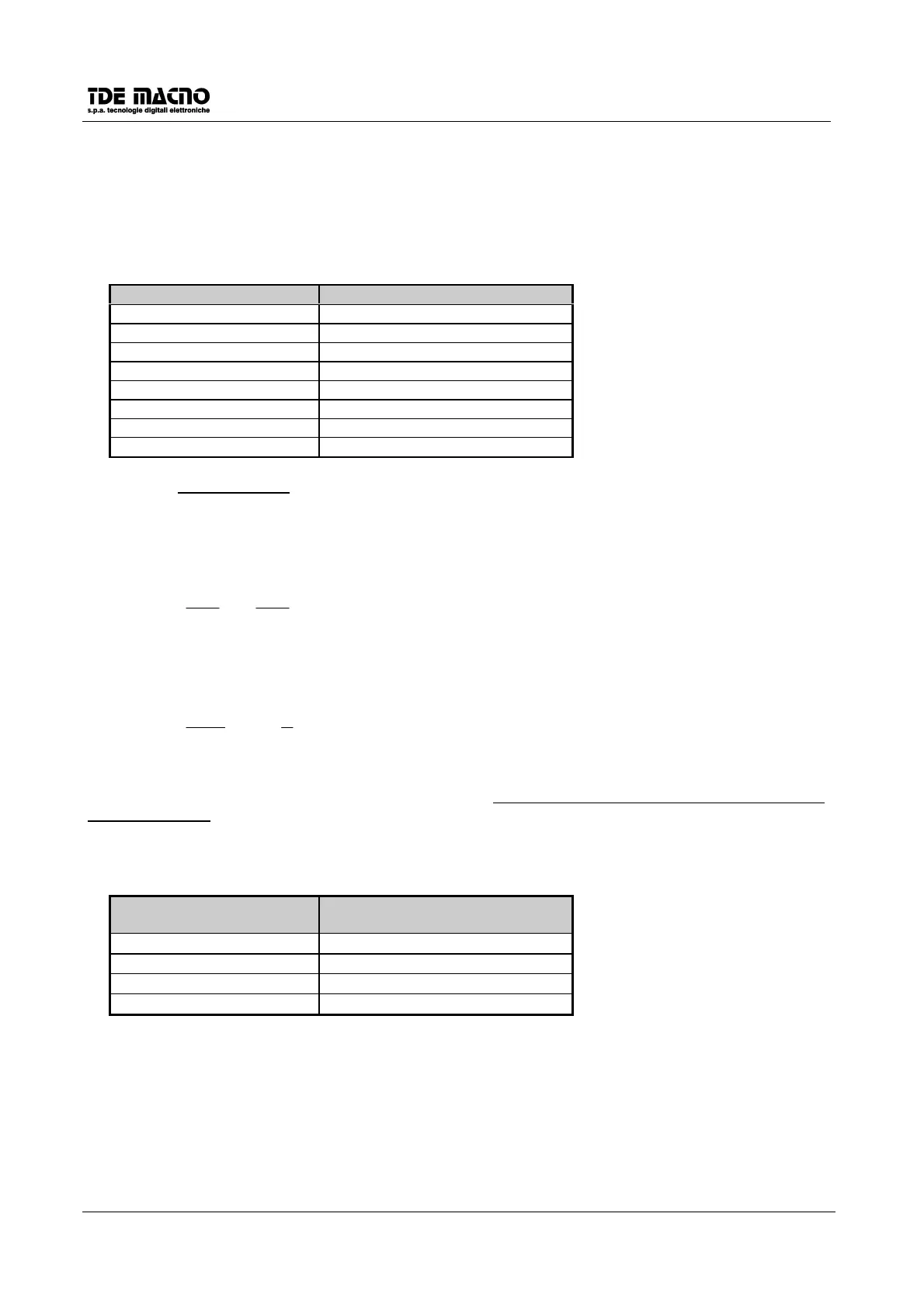
7.4. OUTPUT ENCODER SIMULATION CONFIGURATION
On the connector J3 there are two simulating channels of a bidirectional encoder with a number of pulses for
r.p.m. selectionable with
c11
as indicated in the following table:
c11
Pulse/cycle motor/(
P54/2
)
00
164
2 128
3 256
4 512
5 1024
6 2048
7 4096
The value of default of
c11
=4
as it can be seen the number of pulses depends even on the number of resolver poles, set in the parameter
P54
, and in particular are valid the numbers written above if the resolver is two poles.
The output of the pulses is comanded by a line driver (ET7272), however the choice of the number of pulses
must be done to obtain a maximum frequency for each channel lesser than 500kHz.
Maximum output frequency is computed as follows:
2
54
60
52
P
N
P
Fr
⋅⋅=
, where N is the number of encoder pulses set in
c11
.
Example :
P52 = 3000 c11=5 (1024 pulses per rev.)
P54 = 2 resolver poles
Hz 51200
2
2
1024
60
3000
=⋅⋅=
Fr
The third channel generates a number of zero pulses in phase with channel A, equal to the number of poles
of the resolver divided by two (
P54/2
); in particular there is only one zero pulse for one motor rotation with a
two-pole resolver.
The position of the zero pulse depends from the way it’s connected the resolver on the motor shaft; however
respect to the original position, which corresponds to the resolver zero position, the simulated encoder zero
position can be moved with 90° electric steps with the connection
c12
as indicated in the following table:
c12
resolver
zero pulse shift
0
+0°
1
+90°
2
+180°
3
+270°
The default value is 0.
Those electric degrees corresponds to the mechanical degrees if the resolver is of two poles.
The connection
c10
inverts the channel B of the simulated encoder inverting in this way it’s phase respect to
channel A, for equal sense of rotation (see paragraph 5.4). For default
c10
=0.
 Loading...