User manual 10-1
DSC/DSCT Series
10. SETTING AND CALIBRATION
10.1. ADAPTATION WITH MOTOR
Verify and set:
P54
number of resolver poles: see resolver rating plate or catalog
P53
number of motor poles: see motor rating plate or catalog
P55
resolver phase displacement: refer to the table of the paragraph 10.6
P56
motor nominal current/drive nominal current expressed in percent
(for example if the motor 12A drive 20A
P56
=12/20*100=60.0%)
P57
thermal constant time; if it isn’t noted leave the default value (30sec.)
P58
motor inductance for nominal current: from the motor catalog read the inductance on the terminals
mH and multiply it by the current (for example Imotor=12A L=4mH
P58
=48). If the values aren’t
known leave the parameter of default or execute the autocalibration of the current regulator (
c45
)
(see paragraph 10.5).
P52
set the maximum motor speed in r.p.m. in
P52
: see motor data plate
c34
.
Set the thermal alarm, leave at zero if it’s wanted the continuing function, even with reducted limit,if
it’s necessary the immediate arrest set 1 in case of alarm action
WARNING
: the drive is already tuned to the motor specified at the ordering.
10.2. SETTING REFERENCES AND SPEED LIMITS
The maximum speed equal to ±100.0% of the internal references and ±10V of the analog reference is set at
parameter
P52
directly in revolutions per minute.
All the percentage values set on the speed references, on the speed limits and on the thresholds refer to this
value. This is valid especially for parameters
P01, P02, P03, P05,
P06, P41, P42....
and is also valid for the
'
dxx
' displays.
Ex 1) if
P52
=2000 r.p.m. and a JOG1 speed of 150 r.p.m. is wanted, set:
P01
=150/2000∗100=7.5%
Ex 2) if on
d1
we read a reference of 79.2%, this means that is desired a motor speed of:
79.2/100∗2000=1584 r.p.m.
10.3. SETTING MINIMUM SPEED, MAXIMUM SPEED AND SPEED RANGE SIGNAL LEVEL.
The settings are all in percent and refer to
P52
. The minimum speed logic signal is a signal which is active
when the motor speed in absolute value is greater than the value set at parameter
P41
.
The value is expressed in percentage of the maximum speed.
e.g., if Min speed = 6 r.p.m. and
P52
=2000 r.p.m. is wanted, set:
P41=6/2000∗100=0.3%
The maximum speed alarm occurs when the motor speed exceeds in absolute value that set as parameter at
P42
(in a percent of
P52
).
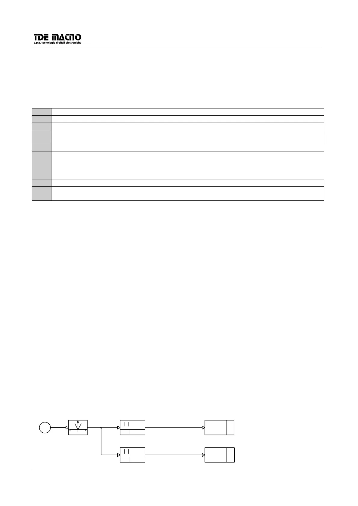
P41
V > P42
MIN. SPEED O11=L
MAX SPEED A9=H
V <=P41
011
A9
MIN
SPEED
MAX
SPEED
V
SPEED (d4)
P42
V max
V min
V