User manual 11-1
DSC/DSCT Series
11. DESCRIPTION OF THE SPEED REGULATION
11.1. EXPLANATION OF THE BLOCK-DIAGRAMS
− The rectangular blocks with
Pxx
represent functions with parameters whose value can be set from the
keypad or from the serial line.
− The switches, opened or closed, indicated with
cxx
represent the internal connections settable by the
keypad or by the serial line, and are indicated in the state corresponding to value "0"
− The connections that can have more than two positions are indicated like commutators whose positions
correspond to the allowed values (the one indicated on the closed line is the default value).
− The open or closed contacts identified with a name (for example REF1) indicate functions operated by
logic inputs or internal logic programmable functions (see ch. "Configurations").
− Internal logic functions normally indicated with a rectangular block
− The circle blocks identified with
dxx
represent the displayed values.
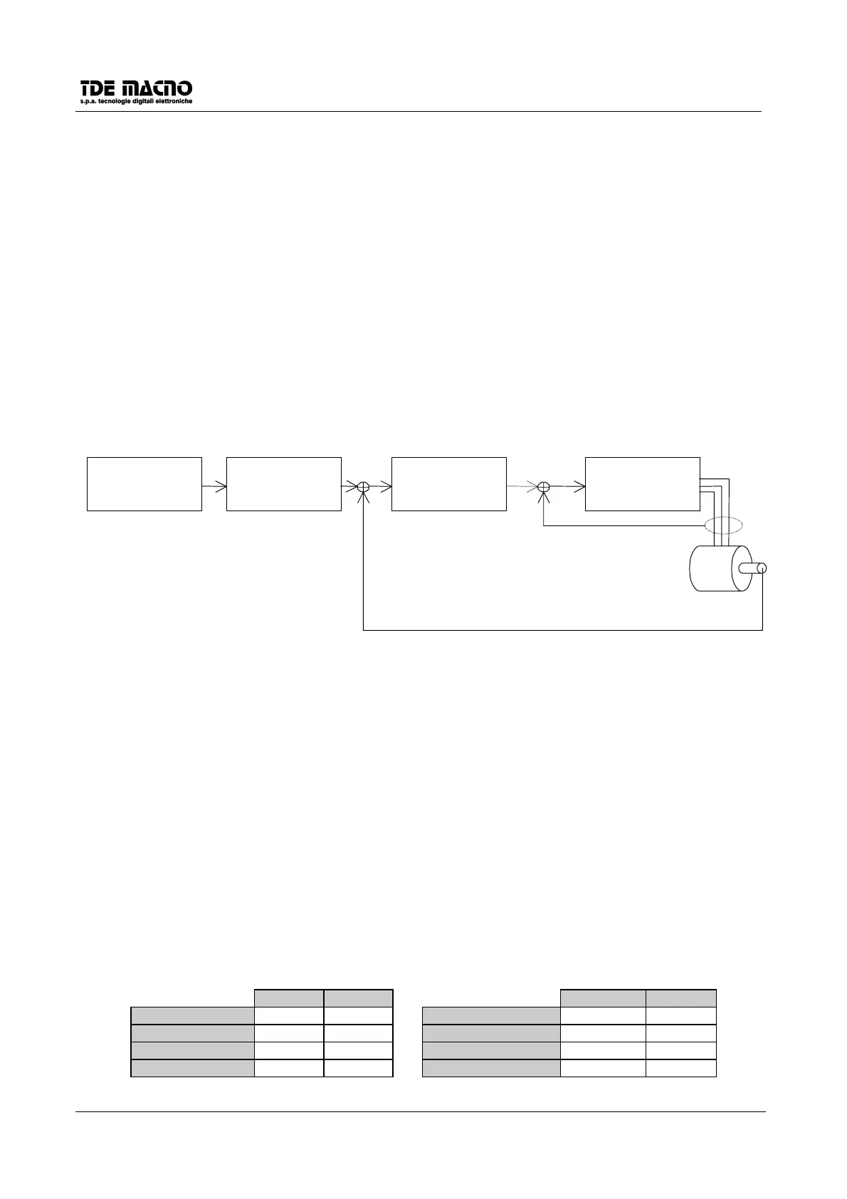
11.2. BLOCK DIAGRAM OF THE REGULATION
Speed reference
block
Linear Ramp
block
Speed regulator
block
Current regulator
block
MOTOR
Speed feedback
from resolver
motor phases
U V W
Current
feedback (U,W)
11.3. SPEED REFERENCE BLOCK
• For the external reference from encoder type frequency option, see chapter 14.
• Up to four speed references are possible, one analog and three digital
• The analog reference, ±10V for the maximum speed, is applied to terminals 11 and 12 of connector J2,
(differential input); if the signal has an offset (maximum ±1,9999V) it can be compensated by means of
parameter
P04
whose value is given in hundreds of microvolts, resolution 1/100000 of the base scale.
• If the maximum speed (set in
P52
) must be reached with an external reference voltage value < 10V, this
value can be set in mV in parameter
P60
(default P60=10000); it should be remembered however that
this operation reduces the reference resolution.
• The three digital references can be set in parameters
P01, P02
and
P03
, with base scale ±100.0% for
the maximum speed; the external reference can be inverted via software by means of connection
c09
(0= not inverted, 1=inverted, default=0).
• The choice between the various references is made by means of inputs REF1EN, REF2EN or
connections
c22
and
c23
according to the following table:
REF1EN REF2EN
c22 c23
Analog REF. H L Analog REF. 1 0
JOG1 LH JOG1 01
JOG2 HH JOG2 11
JOG3 LL JOG3 00
(valid if c22=c23=0) (valid if REF1EN=REF2EN=L)
 Loading...