User manual 9-3
DSC/DSCT Series
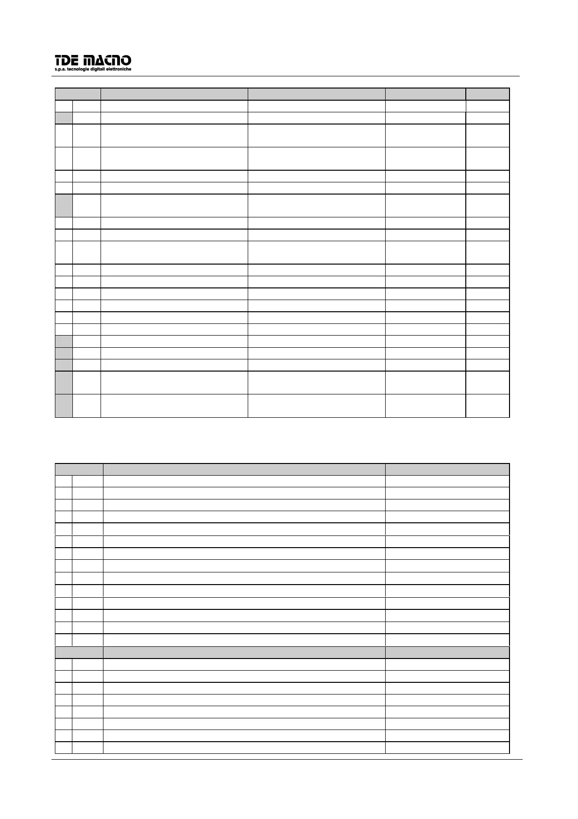
CON. DESCRIPTION FIELD DEFAULT Notes
c 25 Parallel bit to LS2 0(OPEN) 1(CLOSED) 1
c 26 Ramp inclusion 0(excluded) 1(included) 0
c 27 Stop with or without minimum
speed
0(disabled) 1(enabled) 1
c 28 Stop on limit switches with or
without ramp
0(with) 1(without) 0
c 29 Software drive consent 0(alarm) 1(no alarm) 1
c 30 Reset alarms 0(disabled) 1(reset) 0
c 31 External current limit enable (in
series to external enable)
0(disabled) 1(enabled) 0
c 32 Enable torque input 0(disabled) 1(enabled) 0
c 33 relative or absolute speed data 0(relative) 1(absolute) 0
c 34 Motor thermal devices causes
drive block
0(do not stop) 1(stop) 0
c 35 Pos./Speed (0 = Speed. 1 = Pos.) 0 r
c 36 Start Pos. 1 (0 = not active 1 = active) 0
c 37 Start Pos. 2 (0 = not active 1 = active) 0
c 38 Zero search direction (0=CCW,LS2 1 = CW,LS1) 0 n
c 39 relative/absolute positions (0=relative 1=absolute) 0
c 40 SW Zero search command (0 = not active 1 = active) 0
c 41 Reset default values 0(disabled) 1(reset) 0 n
c 42 Reset EEPROM values 0(disabled) 1(reset) 0 n
c 43 EEPROM writing 0(disabled) 1(reset) 0 n
c 44 Resolver phase auto-tuning
command
0(disabled) 1(perform) 0 r
c 45 Current regulator auto-tuning
command
0(disabled) 1(perform) 0 r
Bold
C
indicates the most used parameters that had to be setted in a new installation.
9.3. MAGNITUDES WHICH MAY BE DISPLAYED
DISPLAYS FIELD
d 1 External speed reference % ±100.0%
d 2 Speed ref. before the ramp % ±100.0%
d 3 Speed ref. after the ramp % ±100.0%
d 4 Speed feedback % ±100.0%
d 5 Motor speed in r.p.m. %
0÷19000
d 6 Integral part of the speed regulator % ±100.0%
d 7 Value of the external torque demand signal % ±100.0%
d 8 External current limit %
0÷100.0%
d 9 Last current limit CW %
0÷100.0%
d 10 Last current limit CCW %
0÷(-100.0)%
d 11 Current demand % ±100.0%
d 12 Voltage on the power circuit (V)
0÷999
d 13 Actual position (encoder pulse) mod. 20000
d 14 Resolver reading (encoder pulse)
± 1/2 pulses c11
ALARMS STATE (H=0N L=OFF)
A 1 Internal supply alarm L-H
A 2 RAM, EEPROM alarm L-H
A 3 Power alarm L-H
A 4 Radiator thermal switch alarm L-H
A 5 Motor thermal switch alarm L-H
A 6 Motor in thermal overload L-H
A 7 Resolver failure L-H
A 8 External alarm L-H