User manual 11-4
DSC/DSCT Series
In practice the speed regulator operates with the constants calculated according to the following equations:
Kp = P23 + (P21-P23) * (|V| + |Vrif|) / P20 Proportional gain
Ta = P24 + (P22-P24) * (|V| + |Vrif|) / P20 Advance constant of the speed stage
with: (|V| + |Vrif|) / P20 < 1 where |V| is the absolute value of the speed and |Vrif| is the
absolute value of the reference and P20 is the double value of
the speed to which the constants are to be set.
In this way for special machines the regulator may behave differently at low speed, when the machine friction
may dominate, than at high speed when the inertial torque may be more important. However putting
P20
=0
only
P23
and
P24
are working (default value).
Proportional gains (
P21
,
P23)
are referred to the limit current of the drive: they express the ratio between
current command and speed error; the integral constant and the filter constant are expressed in msec. The
integral action of the speed regulator, which can be seen in the display
d6
, can be excluded by setting the
connection
c20
=1 (default
c20
=0 integral inserted).
With a function generator in the analog reference input the response can be optimised (after the ramp has
been excluded) checking the output TG OUT.
The initial value of the speed regulator integrator can be set to parameter
P27
(scale ±100.0%): this set the
initial current value when the drive is started, to start against brake or with unbalanced loads.
If an analog signal proportional to the unbalance is available, it may be used by connecting it to terminal 9 of
connector J2 (Torque ref) and programming
c32=1
("Torque + speed control" working mode).
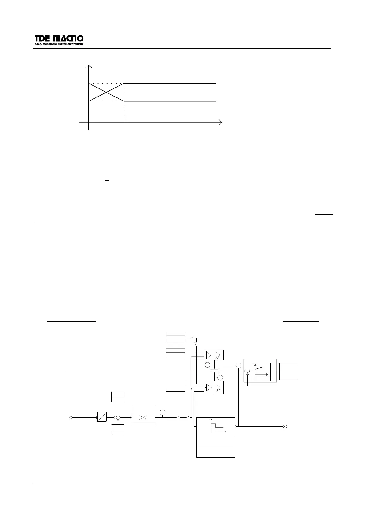
11.6. CURRENT LIMITS
The current reference, after the speed stage output and the torque input, pass through the limiter circuit.
INOM.MOT
P56
C34
A6
MAX CURRENT LIMIT
PWM
IREF
CURRENT REGULATOR
P58=LIN
+
-
D11
KI=P58
D10
D9
P35
CW IMAX
CCW IMAX
P36
PEAK CURRENT LIMIT
I mot
J2-4
IoutImax
In
T
T=2s for Fmot=2.5Hz
0Hz
≤
Fmot
≤
2.5Hz
T=0.3s for Fmot=0Hz
0.3s<T<2s for
OFFSET
P31
A
I.LIMJ2-6
EXTERNAL CURRENT LIMIT
D
CORRECTIVE
COEFFICENT
P34
+
-
C31D8
EXT.LIMIT
OFFSET
P33
FROM SPEED REGULATOR BLOCK
P21
P22
VP20
P24
P23
 Loading...