User manual 7-5
DSC/DSCT Series
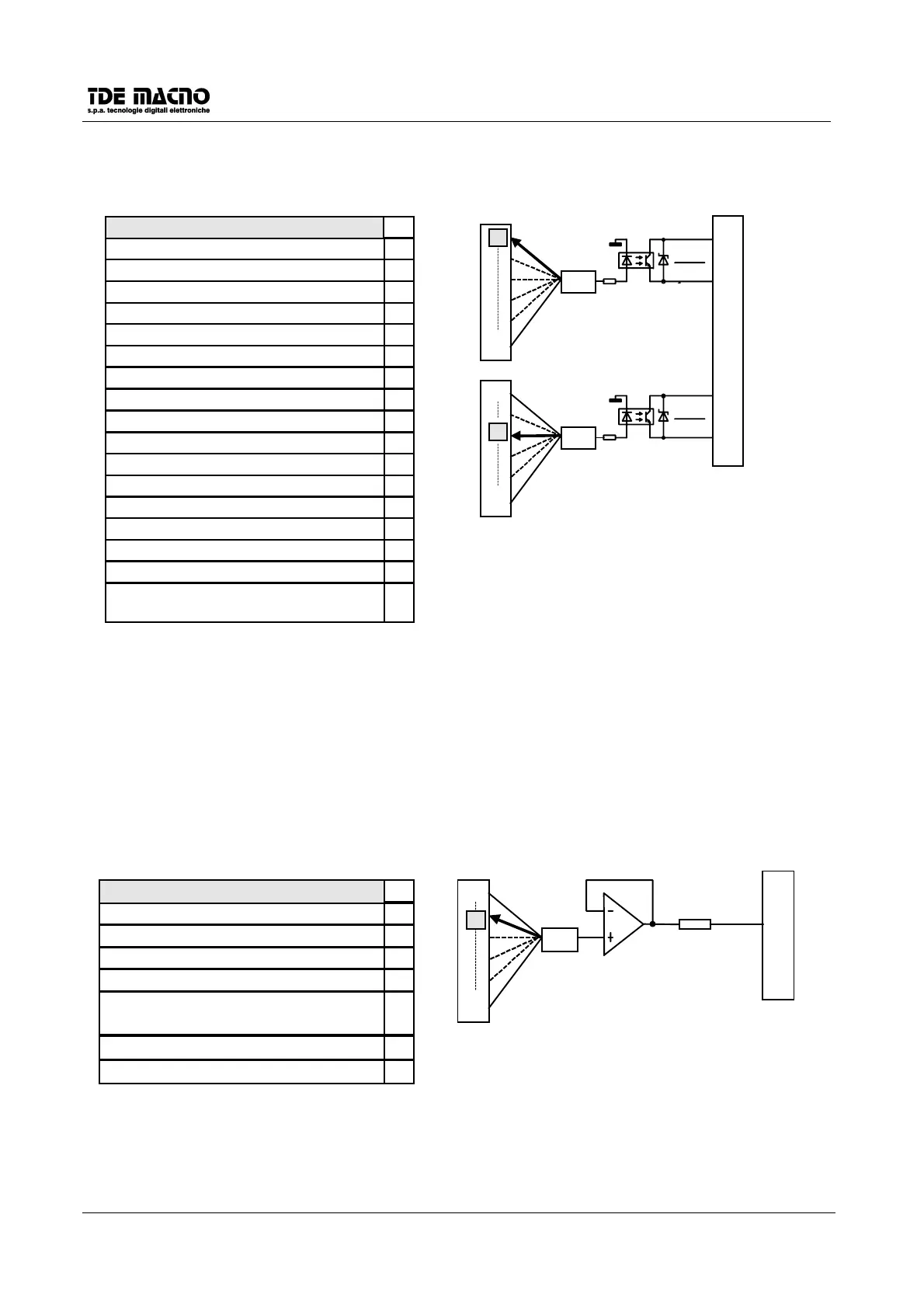
7.2. LOGIC OUTPUTS CONFIGURATION
C07
L.O.1
L.O.
7
8
0
16
C08
L.O.2
L.O.
11
12
0
16
3
J1
AVAILABLE CHOICES
THE THICK LINE INDICATES DEFAULT
PROGRAMMING
DRIVE READY 0
AVAILABLE OUTPUT FUNCTIONS
MOTOR THERMAL ALARM 1
SPEED GREATER THAN MINIMUM 2
DRIVE ON-LINE 3
CW/CCW 4
SPEED REGULATOR SATURATION 5
RAMP END 6
SPEED IN RANGE 7
CURRENT IN RANGE 8
MOTOR BLOCKED 9
STOP IN POSITION 10
RAMP ACTIVE 11
DECELERATION AREA 12
STOP IN POS. 1 13
STOP IN POS.2 14
15
SPEED < P41 AND
POSITION ERROR < 1
16
Maximum current 30mA/24Vcc
In the version DSCT (3x380Vac) the logical output
C07
is not programmable and remains then configurated
as signal of drive ready .
The maximum current is about 30mA.
7.3.
ANALOGIC OUTPUT CONFIGURATION
With the connection
c13
it is possible to read on the programmable analog output at the terminal J2-3 some
of the internal values; in particular are possible the following scheme connections:
A.P.O.1
3
100
Ω
ΩΩ
Ω
c13
1
11
J2
AVAILABLE CHOICES
CURRENT REQUEST 11
THE THICK LINE INDICATES THE
DEFAULT PROGRAMMING
3
EXTERNAL TORQUE REFERENCE 7
SPEED FEEDBACK 4
INTEGRAL PART OF THE SPEED
REGULATOR
6
REFERENCE AFTER THE RAMP 3
REFERENCE BEFORE THE RAMP 2
EXTERNAL SPEED REFERENCE 1
AVAILABLE OUTPUT FUNCTIONS
output
±
±±
±
10V/2mA
 Loading...